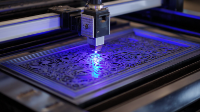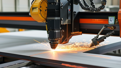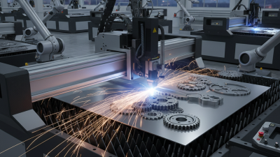


A cnc machine is a computer-controlled tool that turns digital instructions into precise physical movements. It can cut, drill, mill, or shape materials such as aluminum, steel, wood, and plastic. In a modern workshop, a machinist may watch a spindle lower toward a marked block, remove a thin layer, and repeat the motion within a fraction of a millimeter.
The process begins with a computer-aided design model. Software converts that model into toolpaths and machine code, often called G-code. The controller reads each command and directs the motors along specific axes. Cutting speed, feed rate, tool selection, and workholding all influence the final result. Small errors matter. A loose clamp or incorrect offset can ruin an otherwise accurate part.
This guide explains what a cnc machine is, how its main components work, and how a digital drawing becomes a finished object. It also examines common machine types, including mills, lathes, routers, and plasma cutters. Practical safety checks will receive attention because automation does not remove human responsibility. Operators still inspect tools, secure materials, verify programs, and monitor unusual vibration or noise.
CNC machining is powerful.
Yet it is not magic.
Even experienced users can overlook a tool-wear warning or misread a setup dimension. Understanding those limitations makes the technology more reliable. With careful programming, measured adjustments, and disciplined inspection, a cnc machine can produce repeatable parts for manufacturing, engineering, and prototyping.
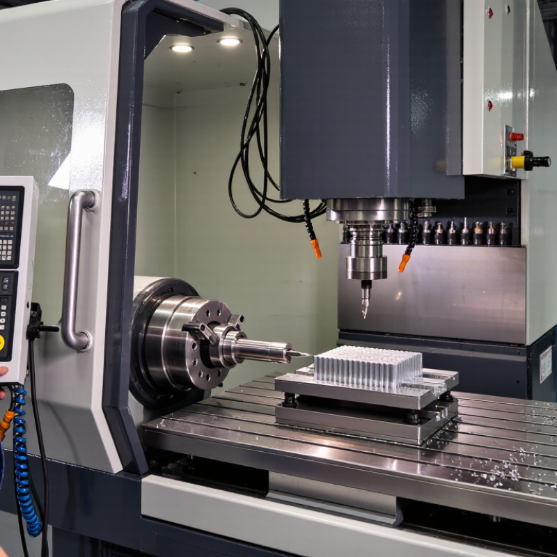
A CNC machine removes material through computer-controlled movements. It follows programmed coordinates instead of relying on constant hand guidance. The cutting tool may drill, mill, turn, or shape metal and plastic.
In practical machining, setup quality often matters as much as machine capability. A loose fixture can ruin an accurate program. Small errors matter.
Axis count describes movement and cutting flexibility.
A 2-axis machine commonly moves across two directions, such as X and Z during turning. A 3-axis machine adds vertical movement, making it suitable for many milled parts.
Four- and five-axis machines rotate the workpiece or cutting tool. They can reach angled surfaces and reduce repeated setups.
More axes do not automatically mean better results. Programming and inspection still decide the outcome.
G-code
G-code tells the machine where to move, how fast to travel, and when to cut. It also controls spindle speed, tool changes, and coolant commands.
A typical instruction may guide a tool toward a precise coordinate. However, code alone cannot correct tool wear, heat growth, vibration, or poor material holding.
A claimed ±0.01 mm accuracy is possible under controlled conditions, but it is not guaranteed on every feature. Temperature changes can affect measurements.
I have found that the final inspection sometimes exposes assumptions hidden during setup.
Calipers may be insufficient, so a micrometer or coordinate measuring equipment can provide stronger evidence.
Precision requires measurement, not confidence.

What Is a CNC Machine and How Does It Work?
A CNC machine turns digital instructions into controlled movements. The process usually begins with a CAD model showing the part’s exact geometry. Engineers define holes, pockets, curves, and critical dimensions before manufacturing begins. The design then moves into CAM software, where cutting tools and machining operations are selected. CAM calculates toolpaths from the model, stock size, fixtures, tool diameter, cutting depth, feed rate, and spindle speed. These details matter. A small setup error can create a costly collision or an inaccurate surface.
CAM does not directly control every machine. A postprocessor converts the calculated toolpaths into machine-readable output, commonly based on ISO 6983, often called G-code. This program contains motion commands, coordinates, tool changes, spindle instructions, and coolant signals. However, ISO 6983 does not guarantee identical behavior on every controller. Machine-specific settings still influence interpretation. Experienced technicians review the code, simulate movements, and check the work offset before cutting. A perfect simulation can still miss a loose fixture or an incorrectly measured tool. That is where practical judgment matters.
Tips: Verify the CAD model before programming. Confirm stock dimensions and fixture clearance. Use simulation to inspect rapid moves and cutting depths. Dry-run the program when possible, with the tool safely above the workpiece. I still recheck the first part manually. It prevents assumptions from becoming scrap.
| Process Stage | Primary Purpose | Typical Input | Main Output | Important Data or Action |
|---|---|---|---|---|
| 1. Part Definition | Describe the required geometry and engineering requirements. | Dimensions, tolerances, material, datum references, and surface requirements. | Manufacturing-ready part requirements. | The design must define the features that need to be produced and inspected. |
| 2. CAD Modeling | Create a digital representation of the part. | 2D sketches, constraints, feature definitions, and solid-model operations. | 3D solid model or 2D drawing geometry. | Common neutral exchange formats include STEP, IGES, and DXF; the chosen format depends on the geometry and workflow. |
| 3. Design Review | Check whether the model can be manufactured as intended. | CAD model, drawing, tolerances, and material information. | Approved or revised design. | Potential issues include inaccessible features, insufficient tool clearance, thin walls, and unsuitable fixturing surfaces. |
| 4. CAM Setup | Convert design information into a machining setup. | CAD geometry, stock dimensions, machine type, workholding, and coordinate system. | Manufacturing setup containing stock, fixtures, tools, and work offsets. | The setup establishes how the part is positioned and how the machine will reference the workpiece. |
| 5. Tool Selection | Choose cutting tools suitable for the material and features. | Workpiece material, feature size, required finish, machine capacity, and tool availability. | Tool list and tool assemblies. | Tool diameter, cutting length, flute count, holder information, and tool number affect the programmed motion. |
| 6. Cutting Parameters | Define how fast and how deeply the tool cuts. | Material, tool data, machine limits, and machining strategy. | Spindle speed, feed rate, plunge rate, step-over, and depth-of-cut values. | Feeds and speeds must be selected within the limits of the tool, workpiece, machine, and workholding system. |
| 7. CAM Toolpath Creation | Calculate the tool movements needed to remove material. | CAD model, stock model, tools, cutting parameters, and machining operations. | Toolpaths for facing, roughing, drilling, contouring, pocketing, or finishing. | Toolpaths may contain rapid moves, cutting moves, arcs, lead-ins, lead-outs, and clearance motions. |
| 8. Simulation and Verification | Identify collisions, excess material, gouges, and unsafe movements before machining. | Toolpaths, machine envelope, fixtures, holders, stock, and workpiece model. | Verified toolpath or a list of required corrections. | Verification reduces risk but does not replace machine setup checks, prove-out procedures, or operator judgment. |
| 9. Post-Processing | Translate CAM toolpaths into machine-specific numerical control instructions. | Verified toolpaths, machine configuration, control settings, and post-processor rules. | NC program commonly associated with ISO 6983-style G-code output. | The output may include coordinate commands, feed commands, spindle commands, tool changes, coolant commands, and program structure. |
| 10. Program Transfer and Setup | Prepare the CNC machine to execute the program safely. | NC program, tools, raw stock, fixtures, work offsets, and inspection equipment. | Loaded program and physically prepared machine. | Operators verify tool lengths, work coordinates, spindle direction, clearances, fixturing, and program revision. |
| 11. Machine Execution | Control axis motion and auxiliary functions during material removal. | NC program and machine feedback signals. | Machined part, chips, coolant activity, and machine status information. | A CNC controller interprets programmed commands and coordinates machine axes, spindle motion, and auxiliary functions. |
| 12. Inspection and Feedback | Confirm that the finished part meets its specified requirements. | Machined part, drawing, gauges, measuring instruments, and inspection plan. | Measured results and corrective actions, if needed. | Inspection feedback may lead to offset adjustments, tool replacement, revised parameters, or updated toolpaths. |
A CNC machine follows digital instructions, but its accuracy comes from the controller’s interpretation of G-code. G-code defines coordinates, feed rates, spindle speed, and tool movements. The controller reads each block, checks machine limits, and converts commands into motion targets.
A command such as
G01 X50 Y20
does not move the tool instantly. It creates a controlled linear path toward those coordinates.
Inside the controller, interpolation calculates thousands of small position updates. Servo drives then send electrical signals to axis motors. Encoders report the actual position, allowing the controller to correct errors continuously. During simultaneous machining, the controller synchronizes X, Y, Z, and rotary axes. Acceleration settings matter. A sharp change can cause vibration, tool marks, or lost accuracy. The machine may look calm, but its calculations are relentless.
Fortune Business Insights reported that the global CNC machine market was valued near 83.9 billion dollars in 2023 and could reach about 128.9 billion dollars by 2032. That growth reflects demand for repeatable, multi-axis production.
Yet reports rarely show the messy shop-floor reality. A slightly wrong tool offset can ruin an otherwise perfect program. Material flex, thermal expansion, and worn cutters also challenge feedback systems. G-code is precise. The real process is less perfect.
A CNC machine follows programmed coordinates to move a cutter through metal, plastic, or wood. Cutting performance depends on three connected choices: spindle speed, feed rate, and tool selection. The 2023 U.S. Manufacturing Technology Orders report recorded more than $5 billion in equipment orders. That figure reflects strong demand, but better output still depends on correct cutting data.
Spindle speed uses surface speed and tool diameter: RPM = cutting speed × 1,000 ÷ π × tool diameter. Smaller tools usually need higher RPM. Feed rate depends on tooth count, chip load, and spindle speed. For example, a four-flute cutter at 0.04 mm chip load and 6,000 RPM needs 960 mm/min. That number is only a starting point. Material hardness, coolant, machine rigidity, and tool overhang can change the result quickly. ISO 3685 tool-life testing shows why cutting conditions must be judged through wear, temperature, and surface quality, not sound alone.
Tips: Begin with conservative settings and inspect the chips. Bright, curled chips often indicate healthy cutting. Blue chips may signal excessive heat. A squealing tool can mean too much speed, weak clamping, or excessive reach. Choose carbide for production stability, coated tools for abrasive materials, and sharp geometry for softer alloys. I still verify the first pass manually; formulas are useful, but they cannot see every weakness in a real setup.
A CNC machine uses programmed instructions to control cutting tools, spindles, and workholding systems. Its controller converts digital coordinates into precise movements along several axes. In practice, accuracy and repeatability are different qualities. Accuracy describes how closely a part matches its intended dimensions. Repeatability describes whether the machine produces the same result again. A machine may repeat a small error consistently. That distinction matters during inspection.
Real workshop results depend on more than the machine itself. Thermal expansion can shift dimensions during long production runs. Tool wear, vibration, chips, and incorrect fixturing can also affect tolerances. Skilled operators check calibration, measure critical features, and adjust cutting conditions when evidence supports it. No machine is perfectly accurate. That assumption causes trouble. Standards such as ISO 230-2 help evaluate positioning performance, but measurement methods and environmental conditions must remain controlled.
Safety requires physical guarding, reliable interlocks, emergency stops, and documented risk assessments. Operators should follow local requirements, training procedures, and energy-isolation practices before maintenance. Standards such as ISO 12100 and ISO 13849 may guide machine risk reduction, while regional regulations can differ. CNC technology supports aerospace, medical-device, automotive, electronics, and general manufacturing applications. Each field demands different tolerances, materials, inspection records, and operator expertise. A tight tolerance on paper may still be unsuitable if the process cannot maintain it repeatedly.
A CNC machine uses computer-controlled commands to move cutting tools along programmed axes and produce repeatable parts from digital designs. The chart shows representative dimensional tolerance ranges commonly used for different CNC operations. Actual results depend on the machine, tooling, material, temperature, workholding, and inspection method.
Lower tolerance values indicate tighter dimensional control. Grinding typically achieves tighter tolerances than general milling, turning, or drilling. Machine accuracy and repeatability should be verified using suitable procedures such as ISO 230-2, while safe operation requires guarding, emergency stops, lockout/tagout practices, and appropriate operator training.


For those larger-sized parts, or smaller quantity runs, we have 2 independent powder coat booths and ovens. The quality, durability and affordability of today’s powder coating finishes make this the process of choice for world-class companies.
Powder coating advantages over other forms of coating are many. Materials used in the Powder coating process can be metals and non-metals that come in a multitude of thicknesses, textures, colors, etc. Another of Powder coating’s biggest advantages over conventional coatings is its ability to create finishes in many different textures. Powder Coating Booths allow us the ability to apply these advantages to large products.
Tri-State Fabricators runs a full-service conveyor line for painting. Wet painting can provide protection or decoration to many different part styles. From start to finish, every project is easier to undergo random and point-based inspection by our skilled painting team.
Advantages to our Wet Paint Line are these lines start with product prep and ends with a thorough inspection of a high quality finished product. Our ability to complete large and small projects with a superior finish and doing so in a timely and economical fashion. This passes along the savings in production to our customers. When powder coating ins not an option, our Wet Paint Line gets the job done right the first time.
When the parts get big and heavy we roll-out our custom paint racks and oversize booth. By utilizing our partnerships with all the major paint brands, we can match virtually any color with wet paint.
The advantages of having access to a Wet Paint Booth are many. Large projects of many different shapes can be loaded into the booth. The Wet Paint Booth offers an environment that is much more controlled than a typical parts painting operation.
Not only are they used because of their controlled environment, but they’re are also advantageous when it comes to applying paint to parts that are needed in industries that require specialty coatings such as medical, aerospace, etc.
Our military forces have some very high standards when it comes to the finish of their vehicles and equipment. From the first pre-treatment step to final coat, it takes a great deal of knowledge and experience to protect the men and women of our armed forces. They deserve only the best, and Tri-State Fabricators provides it.
All of our processes are closely monitored by our staff and management teams. Both of which are highly trained in the processes of metal fabrication and finishing. Tri-State Fabricators’ goal is to always fully satisfy each and every customer, including the military. We will always put a 110% into what we do.
Abrasive media blasting is an excellent way to remove old paint, rust, and increase the paint/powder adhesion. Glass beads produce a much smoother and brighter finish than angular abrasives; leaving the part clean yet without any dimensional change. Chemically inert and environmentally friendly, we can recycle our beads approximately 30 times; making them a more preferred method of metal cleaning or surface finishing.
Advantages to Glass Bead Blasting are many. Glass bead blast media is used when a project is needing rough surfaces need to become smooth for applications of coatings such as paint. It is typically used to clean paint and rust from a product surface without deforming the surface it is being used on. Overall, compared to many other blasting media, Glass Bead Blasting is a very economical choice and those savings are always passed on to our customers.
Tri-State Fabricators utilize a zinc phosphate wash to clean and etch the material to ensure the best paint adhesion possible. The unique design of our 3-stage wash system does the work like a 5-stage. From Cleaning and rinsing to conversion coating and post-treatment, Our Part Washing process is a complete service and works throughout the fabrication service and the finishing service.
Along with the previously mentioned benefits, Curing is a vital chemical reaction that leaves the product finish hard and relatively safe from mild abrasion and aggressive corrosion. This process can be done in more than one way; ambient air-dry or in curing ovens at temps that exceed 240°.
From fixing paint mistakes (someone else’s of course) to simply cleaning our paint line hooks, our burn-off oven is put to good use. After a quick burn-off, a little clean up, and a fresh coat of paint, your parts will look better than new.
Why does our Burn-Off Oven work so well? Because super heating the air around parts turns the materials into ashes. From paint and powder coatings to rubber and machining oils, high temps do the job without degrading the integrity of the part.
Masking is a vital part of producing high quality products. We have die-cut masking patterns to protect machined surfaces as well as a wide range of plugs and caps to protect threaded holes and bolts. We provide permanent and temporary masking.
Masking allows the selected sections of a product to be protected from a fabrication or finishing service. This can be with both chemicals when etching and tapes, paints when only finishing just a section of the product. Masking is great in aiding the customization process of a project.
Screen printing is a photographic process that transfers artwork onto a porous nylon screen which allows colored ink to flow through the screen and be deposited on an aluminum or plastic component. We can generally have just about any design created onto a screen for your parts.
Some of the advantages of Screen Printing are, brand recognition for your business displaying on your products, assembly instructions, product warnings/hazards, etc. Tri-State Fabricators produces Screen Printing of the highest quality so you know it’s durable.
Metal Finishing is the art of treating the exterior portion of product, often metal but can also be made of other materials, so that the surface is clean and free of any debris. Then the process of applying coats or either paint of powder coat takes place. This coating process improves the quality of the product in both appearance and resistance to wear and corrosion.
Tri-State Fabricators, Inc., understands that a project typically isn’t complete until a high-quality finish has been added to your product. This is why our painting and powder coating teams continuously inspect the products throughout the Metal Finishing process.