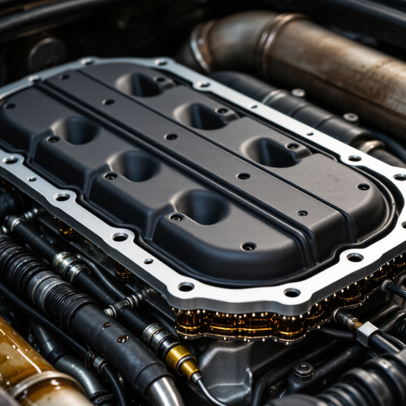
Valve Cover Seals protect the joint between the cylinder head and valve cover, keeping engine oil inside while blocking dirt and moisture. Their failure can leave a thin oil trail along the cover edge, a burnt-oil smell near the exhaust manifold, or visible residue around ignition coils. These symptoms look simple, but the cause is not always simple.
The U.S. Environmental Protection Agency’s Automotive Trends Report shows how modern engines continue pursuing lower emissions and improved efficiency. Tighter engine packaging and higher operating temperatures can place greater demands on sealing materials. Technical guidance from SAE International and ASTM D2000 also highlights the importance of temperature resistance, fluid compatibility, compression set, and elastomer classification. These factors matter when selecting Valve Cover Seals for gasoline, diesel, turbocharged, or hybrid applications.
A seal can harden with age. It can also swell after contact with unsuitable oil additives. Excessive bolt torque may distort the cover and create a leak, even with a new seal. Not every leak means the seal is defective. That distinction is often missed.
Reliable selection begins with the engine code, cover material, operating temperature, and manufacturer specifications. Silicone, molded rubber, and composite designs may perform differently under the same conditions. A workshop inspection should check the cover for warping, damaged bolt grommets, blocked ventilation passages, and uneven clamping. Small details matter.
There is no universal seal.
This guide explains why Valve Cover Seals fail and how to choose replacements with better durability, fit, and sealing performance. It also considers real-world installation mistakes, because even a high-quality part can fail when the surrounding system is ignored.
Why Do Valve Cover Seals Fail and How to Choose Them?
Valve-cover seals come in several forms: molded rubber gaskets, cork-rubber sheets, O-rings, and liquid sealants. Each type suits a different groove, cover design, and service condition. NBR, or nitrile rubber, is widely used because it resists engine oil and offers practical flexibility. Its typical working range is about −40 to 120°C. Short temperature peaks may be acceptable, but continuous heat can accelerate hardening and compression set.
In workshop inspections, leaks often appear near bolt holes and sharp corners. Excessive tightening can flatten the gasket and distort the cover. A scratched sealing surface can cause trouble too. NBR may fail earlier when exposed to severe heat, ozone, or unsuitable fluids. Silicone handles higher temperatures, while FKM generally offers stronger heat and chemical resistance. However, material selection should follow the actual fluid, temperature cycle, groove shape, and compression requirements. A higher-rated material is not automatically better.
Tips: Clean both surfaces before installation. Check the cover for warping with a straightedge. Replace damaged bolts or grommets when needed. Avoid spreading sealant across the entire gasket unless the service procedure requires it. Measure carefully. A seal can look perfect but still leak after a few heat cycles. I have found that installation errors are sometimes mistaken for material failure. That assumption deserves another check.
Valve cover seals fail when heat, oil, and compression gradually change their shape. In workshop inspections, a hardened seal often leaves a thin oil film near bolt corners. That leak may look minor, but repeated heat cycles can turn it into visible seepage.
ASTM D395 compression-set data helps compare how well an elastomer recovers after sustained pressure. A lower compression-set value usually indicates better sealing retention. For example, a seal showing 18% compression set after 22 hours at 125°C may recover more effectively than one reaching 35%. Temperature matters. So does the test method.
Oil resistance requires more than a quick soak. Measure changes in hardness, mass, volume, and tensile strength after exposure to representative engine oil. ASTM D471 is commonly used for liquid immersion, while ASTM D395 evaluates compression recovery. A seal with only 4% volume change may still become too hard for reliable contact. Data must match service temperature and oil type.
Choosing a seal only by hardness is risky. A softer compound may seal uneven flange surfaces, yet lose compression faster. A harder compound may resist extrusion, but leak around a warped cover. I would check compression-set results, oil-induced swelling, and dimensional stability together. Installation errors still matter. Over-tightened bolts can crush the seal before the engine reaches operating temperature. Some test results also fail to predict aging in real traffic, so field inspection remains necessary.
Valve cover seals fail for more reasons than age. Heat hardens rubber, while engine oil can swell an incompatible material. Repeated tightening may also crush the seal and create uneven contact. In workshop inspections, leaks often begin near bolt holes and sharp corners. A clean cover cannot repair poor alignment.
ACM suits many oil-contact applications from −30°C to 150°C. It offers practical resistance and usually works well in moderate engine compartments. However, cold starts below its rated range can make it less flexible.
Silicone handles a wider range, from −60°C to 200°C. It remains flexible in severe cold and tolerates high temperatures, but some oils and fuels may challenge its long-term stability.
FKM covers −20°C to 200°C and provides strong resistance to oils, chemicals, and heat. Its lower cold limit deserves attention in winter climates.
Temperature ratings are not the whole decision.
Check the oil type, cover material, groove depth, compression, and vibration. Measure the old seal before ordering. A seal that feels soft may still be permanently flattened. Do not stretch it around corners. That shortcut often creates a thin, leaking section. I have also seen “high-temperature” choices fail because the groove was dirty. The material choice was reasonable, but the installation was not. Real service conditions are messy, and a perfect rating chart cannot predict every engine bay.
A valve cover seal rarely fails without a reason. Heat hardens the rubber, while oil exposure weakens its elasticity. Incorrect compression can also create a narrow leak path. I have seen new seals leak within days because the groove was packed with old sealant.
Match the seal dimensions to the original equipment specifications. Measure its thickness, width, and corner shape with a caliper. Do not assume a similar-looking seal will fit. The groove must support the seal evenly, without twisting or stretching. Check for cracks, dents, and raised edges around the cover. Clean surfaces matter.
Groove design controls seal movement during tightening. A shallow groove may push the seal outward, while excessive clearance allows it to shift. Follow the specified tightening sequence and torque value. Use a calibrated torque wrench, not hand pressure alone. Tighten gradually in several passes. Too much torque can flatten the seal and distort the cover. Too little torque may leave compression gaps.
A dry fit helps.
Avoid adding sealant unless the service instructions permit it. Extra material can block oil passages or lift the seal from its seat. I once focused too heavily on torque and overlooked a slightly warped cover. That mistake showed me that correct torque cannot repair poor component geometry. Recheck the fastener condition, groove cleanliness, and cover flatness before installation. Small details decide whether the seal remains stable after repeated heat cycles.
Valve cover seals often fail because heat, vibration, and uneven clamping work together. A seal may look flexible during installation, then harden near the hottest cylinder head area. Oil residue around bolt holes can also reveal poor compression. In field inspections, I have found that a clean gasket surface matters as much as the seal material.
Selection should be verified through leak testing, not appearance alone. Install the seal with the specified compression, then apply controlled air pressure to the cover. Use a low-pressure method and inspect joints with a suitable leak-detection fluid. Small bubbles can expose damage hidden beneath a retaining groove. One test is not enough. A single pressure check may miss leaks that appear after thermal expansion.
Heat cycling provides a more realistic challenge. Cycle the assembled cover between cold and operating temperatures, then repeat the leak test. Watch for flattening, cracks, and permanent set along the sealing bead. Service-life data should include temperature limits, compression-set results, and test duration. Ask whether the data represents real engine conditions. Sometimes it does not. I have seen impressive laboratory figures fail to predict aging caused by oil contact and repeated vibration. Choose seals with traceable test records, clear material specifications, and results from both new and aged samples. Track leakage over time, rather than recording only pass or fail.
| Failure or Selection Dimension | Typical Cause or Requirement | Relevant Operating Range or Test Condition | Recommended Verification Method | Representative Acceptance Indicator | Material or Design Guidance |
|---|---|---|---|---|---|
| Thermal aging | Repeated exposure to hot engine oil and cylinder-head heat causes hardening, oxidation, loss of elasticity, and cracking. | Continuous seal temperature commonly falls within approximately 100–150 °C, with short-duration local peaks that may be higher. | Heat-age the assembled seal or material coupons at the intended temperature, followed by hardness, tensile, elongation, and compression-set measurements. | No visible cracks; retained elasticity; compression set remains within the design limit after aging. | Choose an elastomer whose continuous-temperature rating exceeds the measured maximum seal temperature, not only the average engine temperature. |
| Oil and additive compatibility | Engine oil, oxidation products, detergents, and fuel dilution can cause swelling, softening, shrinkage, or embrittlement. | Immerse samples in the specified engine oil at the maximum expected temperature for a defined duration, commonly 168–1,000 hours during development screening. | Measure mass, volume, hardness, tensile strength, elongation, and visual condition before and after immersion. | Limited volume change and no loss of sealing force, cracking, tackiness, or surface disintegration. | NBR is commonly suitable for many petroleum oils; FKM generally provides stronger high-temperature and oil resistance; EPDM is generally unsuitable for petroleum-based engine oil. |
| Compression set | Permanent deformation reduces contact pressure after prolonged compression, especially at high temperature. | Evaluate at the service temperature using a compression-set method such as ASTM D395 or ISO 815-1; test duration is commonly 22–70 hours for screening. | Compare the recovered thickness with the original thickness after controlled cooling and release. | Low compression set relative to the application limit, with sufficient residual contact force around the entire cover perimeter. | Use an appropriate cross-section, controlled squeeze, and adequate flange support; a harder compound is not automatically better if assembly distortion increases. |
| Thermal cycling | Expansion and contraction of the cover, cylinder head, fasteners, and seal repeatedly changes squeeze and can initiate leakage. | Cycle between the minimum cold-start temperature and the maximum measured operating temperature. A development program may use 250–1,000 cycles depending on risk and intended life. | Perform thermal cycling on the complete cover assembly, then inspect for leakage, extrusion, hardening, and permanent deformation. | No visible oil leakage and no loss of sealing continuity after the final cycle and cool-down inspection. | Match seal compression, groove fill, flange stiffness, and material expansion behavior; avoid designs that operate near the minimum squeeze limit when cold. |
| Leak-test sensitivity | Small sealing defects may not appear during a short visual inspection, particularly before oil reaches the joint. | Use a clean, dry assembly and apply a controlled low-pressure air or nitrogen test. Typical screening pressures are application-specific and often remain below 50 kPa. | Use pressure decay, bubble testing, tracer gas, or an oil-run test. The selected method must not deform the cover or seal. | Leak rate is below the project limit at the specified pressure, temperature, and dwell time; no continuous bubble stream is present in a bubble test. | Define the leak limit, test pressure, stabilization time, temperature, and fixture condition before comparing seal designs. |
| Installation damage | Twisting, pinching, over-stretching, sharp casting edges, incorrect groove seating, or sealant contamination can create an immediate leak. | Inspect 100% of prototype assemblies and perform installation trials across the full tolerance range of the cover and cylinder head. | Use visual inspection, dimensional checks, witness marks, and post-installation leak testing. | Seal remains fully seated, untwisted, and continuous; no cut, nick, fold, or extrusion is visible after assembly. | Provide lead-in chamfers, retention features, assembly lubricant compatibility, and poka-yoke features where practical. |
| Fastener load and flange distortion | Uneven torque, excessive torque, insufficient torque, warped flanges, or poor bolt spacing can create local low-pressure zones. | Evaluate the complete torque range, cover flatness tolerance, bolt spacing, and joint stiffness used in production. | Use torque-controlled builds, pressure-sensitive film, gap measurement, or finite-element analysis followed by leak testing. | Continuous contact pressure is maintained around the sealing path without seal extrusion or cover cracking. | Control bolt torque and sequence; design the seal and flange together rather than selecting the elastomer independently. |
| Material selection | The correct compound depends on temperature, oil chemistry, compression behavior, ozone exposure, and manufacturing process. | Typical continuous-temperature guidance: silicone approximately −55 to +175 °C; NBR approximately −30 to +120 °C; ACM approximately −30 to +150 °C; FKM approximately −20 to +200 °C. Actual limits depend on compound and exposure. | Confirm the supplier’s compound data with application-specific oil immersion, thermal aging, compression-set, and assembly tests. | The selected compound meets all temperature, fluid, compression-set, and service-life requirements simultaneously. | Do not select by temperature rating alone; verify low-temperature flexibility, oil compatibility, surface finish, and production tolerances. |
| Low-temperature sealing | A seal that becomes stiff during cold starts may not follow flange movement or maintain sufficient contact pressure. | Test at the lowest specified ambient or cold-start temperature, commonly from approximately −40 to 0 °C depending on vehicle and region. | Cold-soak the assembly, apply the specified joint load, then perform a pressure-decay or oil-leak test during warm-up. | No start-up leakage and no cracking or permanent deformation after returning to room temperature. | Check the compound’s low-temperature flexibility and the seal’s installed compression at the coldest condition. |
| Service-life validation | Early laboratory performance does not guarantee durability under combined heat, oil, vibration, pressure pulses, and assembly tolerances. | Use a combined durability program representing the intended duty cycle; 1,000 hours of accelerated aging or 250–1,000 thermal cycles may be used as development targets, not universal life guarantees. | Run engine or rig testing, periodically measure leak rate, and inspect the seal at scheduled intervals for hardness, cracks, extrusion, and compression loss. | Leak rate remains below the defined limit throughout the test, with no progressive deterioration that indicates field-life risk. | Correlate accelerated results with field data; report test temperature, oil type, duty cycle, squeeze, torque, and failure criteria. |
| Surface finish and cleanliness | Scratches, porosity, machining marks, gasket debris, and oil sludge can form leak paths even when the seal material is suitable. | Inspect the sealing flange and groove across the complete circumference before assembly; use the drawing limits for flatness, roughness, and casting porosity. | Use calibrated dimensional inspection, visual inspection, cleanliness checks, and repeat leak testing after controlled cleaning. | No particles or damage cross the sealing path; surface condition remains within the approved drawing specification. | Define flange and groove requirements on the drawing and prevent uncontrolled use of sealant that can alter compression or contaminate the engine. |
| Production consistency | Variation in elastomer hardness, seal dimensions, molding flash, splice quality, torque, and groove fill can create lot-to-lot leakage. | Monitor critical dimensions, hardness, visual defects, material batch, and assembly torque using statistical process controls. | Perform incoming inspection, first-article validation, periodic leak tests, and traceability review for failed parts. | Critical characteristics remain within control limits and production leak-test results show stable capability. | Define measurable critical-to-quality characteristics and retain samples from each material or molding lot for investigation. |



For those larger-sized parts, or smaller quantity runs, we have 2 independent powder coat booths and ovens. The quality, durability and affordability of today’s powder coating finishes make this the process of choice for world-class companies.
Powder coating advantages over other forms of coating are many. Materials used in the Powder coating process can be metals and non-metals that come in a multitude of thicknesses, textures, colors, etc. Another of Powder coating’s biggest advantages over conventional coatings is its ability to create finishes in many different textures. Powder Coating Booths allow us the ability to apply these advantages to large products.
Tri-State Fabricators runs a full-service conveyor line for painting. Wet painting can provide protection or decoration to many different part styles. From start to finish, every project is easier to undergo random and point-based inspection by our skilled painting team.
Advantages to our Wet Paint Line are these lines start with product prep and ends with a thorough inspection of a high quality finished product. Our ability to complete large and small projects with a superior finish and doing so in a timely and economical fashion. This passes along the savings in production to our customers. When powder coating ins not an option, our Wet Paint Line gets the job done right the first time.
When the parts get big and heavy we roll-out our custom paint racks and oversize booth. By utilizing our partnerships with all the major paint brands, we can match virtually any color with wet paint.
The advantages of having access to a Wet Paint Booth are many. Large projects of many different shapes can be loaded into the booth. The Wet Paint Booth offers an environment that is much more controlled than a typical parts painting operation.
Not only are they used because of their controlled environment, but they’re are also advantageous when it comes to applying paint to parts that are needed in industries that require specialty coatings such as medical, aerospace, etc.
Our military forces have some very high standards when it comes to the finish of their vehicles and equipment. From the first pre-treatment step to final coat, it takes a great deal of knowledge and experience to protect the men and women of our armed forces. They deserve only the best, and Tri-State Fabricators provides it.
All of our processes are closely monitored by our staff and management teams. Both of which are highly trained in the processes of metal fabrication and finishing. Tri-State Fabricators’ goal is to always fully satisfy each and every customer, including the military. We will always put a 110% into what we do.
Abrasive media blasting is an excellent way to remove old paint, rust, and increase the paint/powder adhesion. Glass beads produce a much smoother and brighter finish than angular abrasives; leaving the part clean yet without any dimensional change. Chemically inert and environmentally friendly, we can recycle our beads approximately 30 times; making them a more preferred method of metal cleaning or surface finishing.
Advantages to Glass Bead Blasting are many. Glass bead blast media is used when a project is needing rough surfaces need to become smooth for applications of coatings such as paint. It is typically used to clean paint and rust from a product surface without deforming the surface it is being used on. Overall, compared to many other blasting media, Glass Bead Blasting is a very economical choice and those savings are always passed on to our customers.
Tri-State Fabricators utilize a zinc phosphate wash to clean and etch the material to ensure the best paint adhesion possible. The unique design of our 3-stage wash system does the work like a 5-stage. From Cleaning and rinsing to conversion coating and post-treatment, Our Part Washing process is a complete service and works throughout the fabrication service and the finishing service.
Along with the previously mentioned benefits, Curing is a vital chemical reaction that leaves the product finish hard and relatively safe from mild abrasion and aggressive corrosion. This process can be done in more than one way; ambient air-dry or in curing ovens at temps that exceed 240°.
From fixing paint mistakes (someone else’s of course) to simply cleaning our paint line hooks, our burn-off oven is put to good use. After a quick burn-off, a little clean up, and a fresh coat of paint, your parts will look better than new.
Why does our Burn-Off Oven work so well? Because super heating the air around parts turns the materials into ashes. From paint and powder coatings to rubber and machining oils, high temps do the job without degrading the integrity of the part.
Masking is a vital part of producing high quality products. We have die-cut masking patterns to protect machined surfaces as well as a wide range of plugs and caps to protect threaded holes and bolts. We provide permanent and temporary masking.
Masking allows the selected sections of a product to be protected from a fabrication or finishing service. This can be with both chemicals when etching and tapes, paints when only finishing just a section of the product. Masking is great in aiding the customization process of a project.
Screen printing is a photographic process that transfers artwork onto a porous nylon screen which allows colored ink to flow through the screen and be deposited on an aluminum or plastic component. We can generally have just about any design created onto a screen for your parts.
Some of the advantages of Screen Printing are, brand recognition for your business displaying on your products, assembly instructions, product warnings/hazards, etc. Tri-State Fabricators produces Screen Printing of the highest quality so you know it’s durable.
Metal Finishing is the art of treating the exterior portion of product, often metal but can also be made of other materials, so that the surface is clean and free of any debris. Then the process of applying coats or either paint of powder coat takes place. This coating process improves the quality of the product in both appearance and resistance to wear and corrosion.
Tri-State Fabricators, Inc., understands that a project typically isn’t complete until a high-quality finish has been added to your product. This is why our painting and powder coating teams continuously inspect the products throughout the Metal Finishing process.