

Choosing the Best Inverter Inductor Manufacturers in 2026 requires more than comparing prices or browsing attractive product catalogs. An Inverter Inductor must control current, limit ripple, manage heat, and survive repeated electrical stress. A small core, a tightly wound copper coil, and a few degrees of temperature rise can influence an entire inverter’s reliability.
Dr. Marian K. Kazimierczuk, a recognized power electronics researcher, has stated, “The inductor is one of the most important components in power electronic converters.” This principle guides our evaluation. We examine core materials, saturation current, winding construction, thermal performance, efficiency, testing practices, and customization support. We also consider whether manufacturers provide clear datasheets, sample access, traceable quality systems, and responsive engineering assistance.
The strongest suppliers usually combine advanced equipment with practical production experience. They can explain why a ferrite core suits one frequency, while powdered iron suits another. They should also discuss acoustic noise, insulation spacing, and long-term temperature cycling. These details matter inside solar inverters, electric vehicle chargers, energy storage systems, and industrial drives.
No ranking is perfect. Market data changes, product lines evolve, and some manufacturers disclose limited performance information. A low quoted price may hide higher losses or weaker testing. That uncertainty deserves attention. This guide therefore compares leading manufacturers through technical evidence, application experience, and customer-facing reliability. The goal is not to praise every large brand. It is to identify suppliers that can deliver stable Inverter Inductor performance when real equipment faces heat, vibration, load changes, and time.
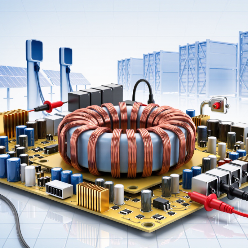
An inverter inductor is a coil of conductive wire wound around a magnetic core. It stores energy in a magnetic field and resists rapid changes in current. In practical terms, it helps smooth the pulsing current produced by power switching. This reduces ripple, limits electromagnetic interference, and supports stable conversion between direct and alternating current.
Core material, winding geometry, and air gap all affect heat, size, and saturation performance. Small design choices matter.
Inductors appear in solar and wind inverters, battery energy storage systems, electric-vehicle power electronics, and industrial motor drives. The International Energy Agency’s Renewables 2024 report recorded about 585 GW of renewable capacity additions worldwide in 2024. Most new capacity came from solar, which depends on inverters to connect generation with electrical systems.
That growth increases demand for reliable magnetic components, though installation totals alone do not predict inductor specifications. Operating frequency, current, temperature, and enclosure space still shape the design.
Tips
Check inductance and saturation-current ratings under real operating conditions, not just at room temperature. Review thermal rise and insulation details, too. A compact inductor may save board space, but run hotter than expected. That trade-off deserves testing. These checks help engineers compare components without relying on headline ratings alone.

Best Inverter Inductor Manufacturers in 2026
Key Criteria for Evaluating Inverter Inductor Manufacturers
Inverter demand is growing alongside renewable power. IRENA’s Renewable Capacity Statistics 2025 reports that the world added 585 GW of renewable capacity in 2024. That scale makes inductor selection a practical reliability decision, not just a price comparison. Ask manufacturers for measured inductance, saturation current, core-loss data, and temperature-rise results at your actual switching frequency. A neat datasheet is not enough.
Check whether test conditions match your inverter’s operating range. Compare thermal performance under sustained load, not only brief laboratory tests. Review winding insulation, vibration resistance, and production traceability, then request sample units for bench testing. Manufacturing consistency matters: small gaps in core assembly can shift inductance and increase noise. Some supplier claims are hard to compare, because test methods may differ. Push for raw test conditions and documented quality-control limits.
Tips: Send manufacturers your waveform, ambient temperature, cooling method, and target lifetime before requesting quotes. Confirm how they handle design changes and failure analysis. A factory visit can help, but it does not replace independent testing. In practice, this step is sometimes skipped. That is worth reconsidering.
Selecting leading inverter inductor manufacturers in 2026 requires more than comparing catalog prices. Look for documented experience with the relevant power range, switching frequency, and operating temperature. Ask how core materials, winding geometry, and insulation are chosen for your application. Good technical support matters when a design runs hot or produces unexpected noise. Ask for test data, not just a polished specification sheet. Details count.
A capable manufacturer should explain saturation current, inductance tolerance, thermal limits, and production testing in clear terms. Check whether samples match production units, and request traceable inspection records for critical dimensions. Lead times and minimum order quantities can change project costs, so confirm them early. Also consider the supplier’s process for handling design changes; a small gap in communication can delay validation. That happens.
Do not assume that the largest factory is automatically the best fit. A smaller, specialized producer may offer useful engineering attention, while its capacity or sourcing flexibility may be limited. Compare several candidates using the same drawings and test conditions. Then review how each responds to technical questions. A confident answer is useful, but evidence is better.
A practical design guideline is to set peak-to-peak inductor current ripple as a percentage of the average inductor current. The values below show representative targets—not manufacturer specifications or universal requirements.
Lower ripple can reduce current stress and filtering demands, but may require a larger inductor. The appropriate target depends on topology, switching frequency, operating conditions, and system requirements.
Inverter inductor manufacturers in 2026 are judged not only by core material, but by how precisely they adapt designs to real operating conditions. IRENA’s Renewable Capacity Statistics 2025 reports that the world added 585 GW of renewable capacity in 2024, bringing the total to 4,448 GW. That growth raises demand for inductors that handle switching ripple, heat, and compact enclosures in solar and energy-storage systems.
Small details matter. A custom design may specify ferrite or powdered-iron cores, winding geometry, insulation, and cooling. Engineers should provide the switching frequency, current waveform, temperature range, and available space before requesting samples. Ask for measured inductance under bias, loss data across operating temperatures, and thermal results from a representative test. A datasheet alone is not enough. For example, a component that fits a 40-millimeter enclosure may still run too hot beside a tightly packed power stage. Customization can improve fit, but it may also extend validation time or require new tooling. That trade-off is easy to underestimate. Independent test conditions and clear tolerance limits make supplier comparisons more reliable.
| Manufacturer Capability Category | Core and Winding Technology | Typical Electrical Range | Thermal and Mechanical Features | Customization Capabilities | Typical Inverter Applications | Common Compliance Requirements | Key Selection Advantage |
|---|---|---|---|---|---|---|---|
| High-Current Powder-Core Specialists | Distributed-gap iron powder, sendust, or alloy powder cores with copper or aluminum windings. | Inductance: approximately 5 µH–5 mH Current: approximately 10–500 A Frequency: typically 10–100 kHz | Low acoustic noise, controlled saturation, robust mechanical construction, and optional forced-air or liquid-cooled assemblies. | Custom gap design Multi-winding layouts Busbar terminals Low-DCR winding | Solar inverters, battery energy-storage converters, motor drives, and high-power DC-link filtering. | IEC 62040, IEC 61800, IEC 61558, RoHS, REACH, and customer thermal-cycle requirements. | High current handling and gradual inductance roll-off near saturation. |
| Ferrite High-Frequency Inductor Producers | MnZn or NiZn ferrite cores, including E, EE, ER, PQ, toroidal, and planar magnetic structures. | Inductance: approximately 1 µH–10 mH Current: approximately 1–100 A Frequency: typically 50 kHz–1 MHz | Low core loss at high switching frequency, compact construction, and insulation systems designed for reinforced isolation. | Core material selection Air-gap adjustment Litz wire Triple insulation | High-frequency DC-DC stages, auxiliary power supplies, telecom rectifiers, and compact inverter modules. | IEC 62368-1, IEC 61558, UL insulation systems, RoHS, REACH, and creepage-clearance requirements. | Efficient operation at elevated switching frequencies and reduced magnetic volume. |
| Common-Mode and Differential-Mode Filter Specialists | Nanocrystalline, ferrite, powdered-iron, or amorphous cores with single-phase, three-phase, or bifilar windings. | Inductance: approximately 10 µH–100 mH Current: approximately 1–300 A Frequency range: application-dependent, from power frequency to several MHz | High impedance to common-mode noise, optimized leakage inductance, flame-retardant bobbins, and reinforced insulation options. | Common-mode design Differential-mode design Three-phase assemblies Integrated capacitors | Grid-tied inverters, EV charging equipment, UPS systems, industrial drives, and electromagnetic-interference filters. | CISPR 11, CISPR 32, IEC 61000 series, IEC 61800-3, and applicable dielectric-strength tests. | Strong conducted-emission suppression and flexible filter integration. |
| Three-Phase AC Output Reactor Manufacturers | Laminated silicon-steel, powdered-core, or composite magnetic structures with three-phase windings. | Inductance: approximately 0.1–10 mH per phase Current: approximately 5–1,000 A System frequency: 50/60 Hz or variable-frequency drive output | Open-frame, enclosed, or cabinet-mounted designs; optional thermal switches, fans, vibration control, and low-noise construction. | Voltage drop adjustment Custom terminals Cabinet integration Thermal sensors | Motor drives, photovoltaic grid interfaces, harmonic filters, industrial power supplies, and regenerative converters. | IEC 60076 principles where applicable, IEC 61800-5-1, IEC 61558, UL 508A integration, and local grid requirements. | Reliable reduction of output ripple, dv/dt stress, and harmonic current. |
| High-Frequency Planar Magnetic Manufacturers | PCB-integrated or laminated planar cores using copper layers, lead frames, or prefabricated planar windings. | Inductance: approximately 0.1 µH–2 mH Current: approximately 5–200 A Frequency: typically 100 kHz–5 MHz | Very low profile, short thermal paths, repeatable winding geometry, and compatibility with automated assembly. | PCB winding design Low-profile packages Integrated thermal vias Custom pin layouts | High-density inverter modules, server power supplies, onboard chargers, and compact energy-storage converters. | IPC-2221, IPC-6012, IEC 62368-1, UL insulation requirements, RoHS, and REACH. | Excellent height control, manufacturing repeatability, and high power density. |
| Automotive-Grade Power Inductor Producers | Molded metal-composite, ferrite, or powder-core constructions with laser-welded or mechanically secured terminals. | Inductance: approximately 1 µH–1 mH Current: approximately 5–150 A Operating temperature: commonly −40°C to +150°C | Vibration-resistant structures, low acoustic noise, high-temperature materials, and controlled thermal derating. | AEC-Q qualification path Custom shielding Automotive terminals PPAP support | Electric-vehicle traction inverters, onboard chargers, DC-DC converters, battery-management power stages, and auxiliary drives. | AEC-Q200, IATF 16949, ISO 26262-related customer processes, ISO 16750, RoHS, and REACH. | Strong reliability under vibration, thermal cycling, and automotive qualification requirements. |
| Liquid-Cooled High-Power Magnetic Assembly Providers | Powder-core, ferrite, laminated-steel, or nanocrystalline cores integrated with copper tubing, cold plates, or cast cooling channels. | Inductance: approximately 10 µH–20 mH Current: approximately 100–3,000 A Power level: multi-kilowatt to megawatt-class systems | Direct liquid cooling, high thermal conductivity interfaces, reinforced insulation, and custom mounting frames. | Cooling-channel design Busbar integration Pressure testing System enclosure | Utility-scale solar inverters, grid-forming converters, large battery systems, hydrogen power electronics, and industrial drives. | IEC 62477-1, IEC 61800-5-1, IEC 60529 for enclosure protection, pressure-test specifications, and site-specific grid codes. | High continuous-current capability with improved thermal performance and reduced enclosure size. |
| Rapid-Prototyping and Low-to-Medium Volume Custom Manufacturers | Flexible use of ferrite, powder, nanocrystalline, laminated, and composite core platforms according to prototype requirements. | Inductance and current ratings defined by the customer design; commonly from sub-µH prototypes to several hundred amperes. | Engineering samples, adjustable mechanical interfaces, configurable insulation systems, and design-for-manufacturing feedback. | Prototype turns Custom drawings Thermal simulation Small-batch builds | New inverter topologies, laboratory converters, aerospace demonstrators, university research, and pre-production validation. | Customer-specific validation plans, insulation testing, RoHS, REACH, and applicable IEC or UL requirements. | Shorter development cycles and flexible engineering support before volume production. |
Choosing an inductor manufacturer starts with your inverter’s actual operating conditions, not a catalogue headline. Define current, switching frequency, temperature range, ripple limits, and available space. Then ask for core-loss curves and saturation-current data across the temperatures your equipment will face. A component that passes a room-temperature test may behave differently inside a hot enclosure. Small detail. Big consequence.
IEA PVPS’s Snapshot of Global PV Markets 2024 estimated that worldwide solar photovoltaic capacity exceeded 1.6 terawatts by the end of 2023. That expanding installed base makes dependable components and repeatable production increasingly important.
Compare manufacturers on documented quality controls, traceability, sample consistency, and realistic lead times. Request test reports for inductance, resistance, temperature rise, and noise under conditions resembling your design. Check whether engineering support can review a winding or core change before production. A polished datasheet alone is not proof; I would still want independent measurements.
Tips: Send shortlisted suppliers the same specification and sample-test plan. Compare results, not promises. Ask how they manage material substitutions and production-lot variation. If a supplier cannot explain its test setup clearly, pause. It may be a minor communication gap, or a warning worth investigating.


For those larger-sized parts, or smaller quantity runs, we have 2 independent powder coat booths and ovens. The quality, durability and affordability of today’s powder coating finishes make this the process of choice for world-class companies.
Powder coating advantages over other forms of coating are many. Materials used in the Powder coating process can be metals and non-metals that come in a multitude of thicknesses, textures, colors, etc. Another of Powder coating’s biggest advantages over conventional coatings is its ability to create finishes in many different textures. Powder Coating Booths allow us the ability to apply these advantages to large products.
Tri-State Fabricators runs a full-service conveyor line for painting. Wet painting can provide protection or decoration to many different part styles. From start to finish, every project is easier to undergo random and point-based inspection by our skilled painting team.
Advantages to our Wet Paint Line are these lines start with product prep and ends with a thorough inspection of a high quality finished product. Our ability to complete large and small projects with a superior finish and doing so in a timely and economical fashion. This passes along the savings in production to our customers. When powder coating ins not an option, our Wet Paint Line gets the job done right the first time.
When the parts get big and heavy we roll-out our custom paint racks and oversize booth. By utilizing our partnerships with all the major paint brands, we can match virtually any color with wet paint.
The advantages of having access to a Wet Paint Booth are many. Large projects of many different shapes can be loaded into the booth. The Wet Paint Booth offers an environment that is much more controlled than a typical parts painting operation.
Not only are they used because of their controlled environment, but they’re are also advantageous when it comes to applying paint to parts that are needed in industries that require specialty coatings such as medical, aerospace, etc.
Our military forces have some very high standards when it comes to the finish of their vehicles and equipment. From the first pre-treatment step to final coat, it takes a great deal of knowledge and experience to protect the men and women of our armed forces. They deserve only the best, and Tri-State Fabricators provides it.
All of our processes are closely monitored by our staff and management teams. Both of which are highly trained in the processes of metal fabrication and finishing. Tri-State Fabricators’ goal is to always fully satisfy each and every customer, including the military. We will always put a 110% into what we do.
Abrasive media blasting is an excellent way to remove old paint, rust, and increase the paint/powder adhesion. Glass beads produce a much smoother and brighter finish than angular abrasives; leaving the part clean yet without any dimensional change. Chemically inert and environmentally friendly, we can recycle our beads approximately 30 times; making them a more preferred method of metal cleaning or surface finishing.
Advantages to Glass Bead Blasting are many. Glass bead blast media is used when a project is needing rough surfaces need to become smooth for applications of coatings such as paint. It is typically used to clean paint and rust from a product surface without deforming the surface it is being used on. Overall, compared to many other blasting media, Glass Bead Blasting is a very economical choice and those savings are always passed on to our customers.
Tri-State Fabricators utilize a zinc phosphate wash to clean and etch the material to ensure the best paint adhesion possible. The unique design of our 3-stage wash system does the work like a 5-stage. From Cleaning and rinsing to conversion coating and post-treatment, Our Part Washing process is a complete service and works throughout the fabrication service and the finishing service.
Along with the previously mentioned benefits, Curing is a vital chemical reaction that leaves the product finish hard and relatively safe from mild abrasion and aggressive corrosion. This process can be done in more than one way; ambient air-dry or in curing ovens at temps that exceed 240°.
From fixing paint mistakes (someone else’s of course) to simply cleaning our paint line hooks, our burn-off oven is put to good use. After a quick burn-off, a little clean up, and a fresh coat of paint, your parts will look better than new.
Why does our Burn-Off Oven work so well? Because super heating the air around parts turns the materials into ashes. From paint and powder coatings to rubber and machining oils, high temps do the job without degrading the integrity of the part.
Masking is a vital part of producing high quality products. We have die-cut masking patterns to protect machined surfaces as well as a wide range of plugs and caps to protect threaded holes and bolts. We provide permanent and temporary masking.
Masking allows the selected sections of a product to be protected from a fabrication or finishing service. This can be with both chemicals when etching and tapes, paints when only finishing just a section of the product. Masking is great in aiding the customization process of a project.
Screen printing is a photographic process that transfers artwork onto a porous nylon screen which allows colored ink to flow through the screen and be deposited on an aluminum or plastic component. We can generally have just about any design created onto a screen for your parts.
Some of the advantages of Screen Printing are, brand recognition for your business displaying on your products, assembly instructions, product warnings/hazards, etc. Tri-State Fabricators produces Screen Printing of the highest quality so you know it’s durable.
Metal Finishing is the art of treating the exterior portion of product, often metal but can also be made of other materials, so that the surface is clean and free of any debris. Then the process of applying coats or either paint of powder coat takes place. This coating process improves the quality of the product in both appearance and resistance to wear and corrosion.
Tri-State Fabricators, Inc., understands that a project typically isn’t complete until a high-quality finish has been added to your product. This is why our painting and powder coating teams continuously inspect the products throughout the Metal Finishing process.