


Choosing a Centering Machine is not just a matter of comparing prices or selecting the fastest model. The right equipment should match the workpiece, production volume, and accuracy your process actually requires. A small variation in diameter, material, or clamping method can affect alignment and repeatability. Details matter.
Before evaluating machines, consider the parts you run each day and the changes your team may face later. Note workpiece dimensions, required tolerances, cycle time, available floor space, and operator experience. Ask suppliers how setup, calibration, tooling changes, and routine maintenance work in practice. Request a demonstration using representative parts, not only a polished sample. That can reveal awkward loading, vibration, or adjustments that take longer than expected.
This guide presents seven practical tips for comparing machine capability, control options, build quality, service support, and total operating cost. It also explains why a low purchase price may not reflect the cost of downtime or specialized tooling. Keep records from trials and verify claims against your own requirements. No specification sheet can answer every question. Some trade-offs only become clear on the shop floor, and even experienced buyers may need to revise their assumptions. Use these tips as a structured starting point, then confirm important decisions with qualified technical staff and the machine supplier.
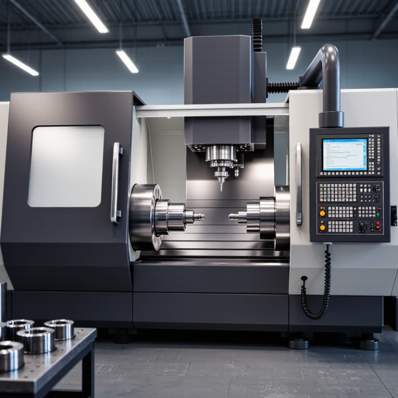
Classify each workpiece before comparing centering machines. Record diameter ranges, material, and required centering tolerance. A 10 mm lens and a 50 mm lens can react differently to the same holding force. Glass may chip at an edge; thin metal parts can flex in a chuck. These are practical screening factors, not universal rules. Verify them with representative samples.
ISO 10110-6:2015 defines how optical centering tolerances are specified; use the drawing’s stated tolerance rather than assuming a machine’s advertised resolution is sufficient. Separate eccentricity from tilt when reviewing the requirement, then check whether the machine can measure and correct both. A common shop-floor mistake is treating indicated runout as the whole tolerance. It isn’t. For measurement records, NIST Technical Note 1297 describes expanded uncertainty as U = kuc; k = 2 provides roughly 95% coverage under suitable conditions. Include that uncertainty when judging whether a result meets specification. This detail is easy to miss. Recheck it. Keep actual workpiece data, since nominal diameter alone may not reveal clamping distortion.

7 Tips for Choosing the Best Centering Machine
Set runout and repeatability limits in micrometers using the part drawing, not a machine brochure. Identify the feature being centered, its datum, and the applicable runout tolerance. A 12 μm runout limit, for example, does not automatically mean the machine needs 12 μm repeatability. Fixturing, probing, and measurement uncertainty also affect the finished result. Leave a practical margin.
Tips: Check the drawing’s datum scheme before setting limits. Compare machine repeatability with the tightest relevant tolerance, then confirm the result using the same measurement method used in production. If a drawing allows 20 μm of runout, a process target of 10 μm may provide room for variation—but only if setup and inspection support it. Measure twice.
Record results across several parts and setups. A single good reading can hide drift from temperature changes, worn locating surfaces, or inconsistent clamping. Watch both the average and the spread. One caution: drawings sometimes leave the inspection method unclear. Ask for clarification rather than guessing; otherwise, a precise machine can still produce disputed measurements. Recheck limits when the part, fixture, or process changes.
How to use this table: The figures below are illustrative selection targets, not universal standards. Derive final limits from the part drawing, datum scheme, process capability needs, and measurement uncertainty.
| Tip | What to Check | Example Drawing Requirement | Example Machine Screening Target | How to Verify |
|---|---|---|---|---|
| 1 | Translate the drawing’s datum and runout callouts into a measurable setup requirement. | Total indicated runout (TIR) at a functional cylindrical feature: ≤20 μm relative to the specified datum axis. | Workholding and centering contribution: ≤4 μm TIR under the defined setup conditions. | Indicate the reference feature at the specified measurement plane and document the setup. |
| 2 | Set repeatability limits separately from absolute accuracy. | Part feature position must remain within a 10 μm process window across repeated setups. | Repeated centering variation: ≤2 μm range across a representative series of cycles. | Repeat the load-center-unload cycle with the same part and measurement method; report the sample size and range. |
| 3 | Confirm the machine can handle the complete part envelope and datum locations. | Example part: 8–40 mm diameter, 120 mm long, with the centering datum 75 mm from the end. | Chuck, support, and sensing arrangement must cover the part dimensions without obstructing the datum or measurement point. | Run a fit check using representative parts, including the longest and smallest-diameter cases. |
| 4 | Assess how clamping force and contact geometry affect the part. | Thin-wall component: 1.0 mm nominal wall; drawing permits no more than 8 μm change in measured roundness after clamping. | Clamping-induced change should be controlled and repeatable; establish a validated force range for the part family. | Compare roundness or diameter measurements before and after clamping at the approved force setting. |
| 5 | Match the centering method and sensor to the part surface and required resolution. | Centering error budget: 5 μm; datum surface may include a fine ground finish. | Measurement resolution should be finer than the allocated error budget, and the sensing method must suit the surface, material, and geometry. | Review sensor resolution, contact force or optical setup, calibration status, and performance on a representative surface. |
| 6 | Check performance at the intended operating speed, load, and production duty cycle. | Process requires stable centering over 200 parts per shift, with a 15 μm maximum runout at the finished feature. | Runout and repeatability must remain within the process allocation during sustained operation, not only during a short idle test. | Perform a production-representative trial and record results at the start, middle, and end of the run. |
| 7 | Require a practical verification and maintenance plan. | Example acceptance limit at final inspection: TIR ≤15 μm at the drawing-defined location. | Provide a documented method to check setup performance with a suitable reference artifact; measurement uncertainty should be considered when setting acceptance limits. | Review the acceptance protocol, reference-artifact calibration, check frequency, and corrective-action procedure. |
A centering machine can look precise on a brochure, but ISO 230-2 test data gives you a more useful comparison. The standard describes methods for measuring axis positioning accuracy and repeatability. Ask for the actual test report, not just a single accuracy figure. Check the tested axis, travel range, measurement direction, and ambient conditions. A result measured over a short stroke may not represent performance near the ends of your working range.
Compare bidirectional results, since an axis may behave differently when approaching a point from opposite directions. Look for positioning deviation and repeatability across several target positions. Small differences matter. For example, a reported deviation of a few micrometres could affect how consistently a component sits against the machine’s centering stops.
Confirm whether the values are measured before or after compensation, and whether the test setup used calibrated measuring equipment. The chart is not the whole story. ISO 230-2 data describes axis behavior under stated test conditions; it does not guarantee finished-part accuracy in every setup. Ask how temperature, fixture alignment, and workpiece variation are controlled during your own production checks. A missing condition in the report is worth asking about.
Estimate a centering machine from measured cycle time, not the catalog rate. If one part takes 18 seconds, an eight-hour shift has a theoretical ceiling of 1,600 parts. That assumes uninterrupted running. It ignores setup, loading, inspection, tool changes, and rejected parts. For a more useful estimate, subtract planned breaks and changeovers, then apply observed uptime and first-pass yield.
Batch size changes the picture. A 600-part batch may need several minutes of setup before the first piece is produced. Record setup time separately, especially when jobs switch between different diameters or materials. Then calculate:
usable production minutes × 60 ÷ cycle seconds × good-part rate.
Compare that figure with required daily volume, and keep a buffer for normal variation. Small delays matter. A slightly optimistic cycle-time estimate can leave a real order short.
Industry figures offer context, not a machine-specific promise. Deloitte’s 2025 Smart Manufacturing Survey reported production-output improvements of 10–20% among surveyed manufacturers adopting smart manufacturing technologies. Those gains are not a centering-machine benchmark. Track actual cycle times across several shifts, including a difficult batch, and revise the estimate when the data disagree. I would not trust one unusually smooth run. It feels convincing, but it may hide the interruptions that define an ordinary day.
A centering machine should prove repeatable performance on your actual parts, not just a polished sample. Request a capability study using the material, geometry, fixture, and operating conditions you expect in production.
NIST’s Engineering Statistics Handbook explains that capability indices are meaningful only when the process is stable and the data meet the method’s assumptions. Cpk of 1.33 is a common acceptance target, not a universal guarantee. Check the control chart, sample coverage, and distance to both specification limits. A strong average can hide drift.
Then examine the measurement system. The AIAG Measurement Systems Analysis Reference Manual, 4th edition, generally considers Gauge R&R below 10% acceptable; 10–30% may need justification, depending on the application. Confirm whether the reported percentage is based on study variation or tolerance. Keep that basis consistent.
Numbers need context. For a practical trial, have different operators repeatedly center parts, remove and reload them, and record readings across the working range. Watch the fixture contact points and the display’s smallest increment.
If measurement noise consumes too much of the tolerance, an impressive Cpk may simply reflect a weak gauge. Ask for raw data and rerun the study after adjustments. Even then, one successful trial is not proof of long-term performance.


For those larger-sized parts, or smaller quantity runs, we have 2 independent powder coat booths and ovens. The quality, durability and affordability of today’s powder coating finishes make this the process of choice for world-class companies.
Powder coating advantages over other forms of coating are many. Materials used in the Powder coating process can be metals and non-metals that come in a multitude of thicknesses, textures, colors, etc. Another of Powder coating’s biggest advantages over conventional coatings is its ability to create finishes in many different textures. Powder Coating Booths allow us the ability to apply these advantages to large products.
Tri-State Fabricators runs a full-service conveyor line for painting. Wet painting can provide protection or decoration to many different part styles. From start to finish, every project is easier to undergo random and point-based inspection by our skilled painting team.
Advantages to our Wet Paint Line are these lines start with product prep and ends with a thorough inspection of a high quality finished product. Our ability to complete large and small projects with a superior finish and doing so in a timely and economical fashion. This passes along the savings in production to our customers. When powder coating ins not an option, our Wet Paint Line gets the job done right the first time.
When the parts get big and heavy we roll-out our custom paint racks and oversize booth. By utilizing our partnerships with all the major paint brands, we can match virtually any color with wet paint.
The advantages of having access to a Wet Paint Booth are many. Large projects of many different shapes can be loaded into the booth. The Wet Paint Booth offers an environment that is much more controlled than a typical parts painting operation.
Not only are they used because of their controlled environment, but they’re are also advantageous when it comes to applying paint to parts that are needed in industries that require specialty coatings such as medical, aerospace, etc.
Our military forces have some very high standards when it comes to the finish of their vehicles and equipment. From the first pre-treatment step to final coat, it takes a great deal of knowledge and experience to protect the men and women of our armed forces. They deserve only the best, and Tri-State Fabricators provides it.
All of our processes are closely monitored by our staff and management teams. Both of which are highly trained in the processes of metal fabrication and finishing. Tri-State Fabricators’ goal is to always fully satisfy each and every customer, including the military. We will always put a 110% into what we do.
Abrasive media blasting is an excellent way to remove old paint, rust, and increase the paint/powder adhesion. Glass beads produce a much smoother and brighter finish than angular abrasives; leaving the part clean yet without any dimensional change. Chemically inert and environmentally friendly, we can recycle our beads approximately 30 times; making them a more preferred method of metal cleaning or surface finishing.
Advantages to Glass Bead Blasting are many. Glass bead blast media is used when a project is needing rough surfaces need to become smooth for applications of coatings such as paint. It is typically used to clean paint and rust from a product surface without deforming the surface it is being used on. Overall, compared to many other blasting media, Glass Bead Blasting is a very economical choice and those savings are always passed on to our customers.
Tri-State Fabricators utilize a zinc phosphate wash to clean and etch the material to ensure the best paint adhesion possible. The unique design of our 3-stage wash system does the work like a 5-stage. From Cleaning and rinsing to conversion coating and post-treatment, Our Part Washing process is a complete service and works throughout the fabrication service and the finishing service.
Along with the previously mentioned benefits, Curing is a vital chemical reaction that leaves the product finish hard and relatively safe from mild abrasion and aggressive corrosion. This process can be done in more than one way; ambient air-dry or in curing ovens at temps that exceed 240°.
From fixing paint mistakes (someone else’s of course) to simply cleaning our paint line hooks, our burn-off oven is put to good use. After a quick burn-off, a little clean up, and a fresh coat of paint, your parts will look better than new.
Why does our Burn-Off Oven work so well? Because super heating the air around parts turns the materials into ashes. From paint and powder coatings to rubber and machining oils, high temps do the job without degrading the integrity of the part.
Masking is a vital part of producing high quality products. We have die-cut masking patterns to protect machined surfaces as well as a wide range of plugs and caps to protect threaded holes and bolts. We provide permanent and temporary masking.
Masking allows the selected sections of a product to be protected from a fabrication or finishing service. This can be with both chemicals when etching and tapes, paints when only finishing just a section of the product. Masking is great in aiding the customization process of a project.
Screen printing is a photographic process that transfers artwork onto a porous nylon screen which allows colored ink to flow through the screen and be deposited on an aluminum or plastic component. We can generally have just about any design created onto a screen for your parts.
Some of the advantages of Screen Printing are, brand recognition for your business displaying on your products, assembly instructions, product warnings/hazards, etc. Tri-State Fabricators produces Screen Printing of the highest quality so you know it’s durable.
Metal Finishing is the art of treating the exterior portion of product, often metal but can also be made of other materials, so that the surface is clean and free of any debris. Then the process of applying coats or either paint of powder coat takes place. This coating process improves the quality of the product in both appearance and resistance to wear and corrosion.
Tri-State Fabricators, Inc., understands that a project typically isn’t complete until a high-quality finish has been added to your product. This is why our painting and powder coating teams continuously inspect the products throughout the Metal Finishing process.