

10 Tips for Choosing CNC Cutting Tools

Choosing Cnc Cutting Tools is not a matter of picking the hardest insert or the cheapest end mill. It is a practical decision shaped by material, machine rigidity, spindle speed, coolant, and production goals. A tool that performs well in aluminum may fail quickly in hardened steel. Even a premium cutter can chatter when runout, workholding, or chip load is ignored.

Dr. Tony L. Schmitz, a respected machining researcher, offers a useful principle: “The process is the product.” That idea keeps tool selection connected to the entire cutting system, not just the tool catalog. This guide examines ten practical considerations, including tool material, coating, geometry, flute count, edge preparation, cutting speed, feed rate, tool overhang, coolant delivery, and expected tool life. Small details matter. A 0.01 mm runout can create uneven tooth loading. A long, unsupported end mill can turn a clean slot into a vibrating, overheated surface.

Real workshops rarely behave perfectly. Operators may begin with conservative settings, then adjust them after watching chips, sound, and surface finish. That judgment comes from experience, but it should still be checked against manufacturer data and machine limits. There is no universal “best” cutter. Sometimes the recommended tool is not available, or the first trial simply performs poorly. That result is useful, if recorded honestly.

The following tips provide a dependable starting point for selecting Cnc Cutting Tools, improving consistency, and reducing avoidable tool failure. The process deserves attention. The tool is only one part.
10 Tips for Choosing CNC Cutting Tools

Identify the Material, Machine, and Cutting Requirements

10 Tips for Choosing CNC Cutting Tools

Identify the Material, Machine, and Cutting Requirements

Begin with the workpiece material, not the tool catalog. Aluminum, stainless steel, hardened steel, plastics, and composites behave differently under heat and pressure. Check hardness, abrasiveness, toughness, and thermal conductivity before selecting tool material or geometry. A sharp edge may reduce cutting force in soft aluminum. A stronger edge usually survives interrupted cuts in hard steel. Review the material certificate when available. Guessing can waste both tools and parts.

Match the cutter to the machine’s real capacity. Check spindle speed, available torque, taper, tool-holding quality, axis travel, and coolant delivery. A high-speed tool is ineffective when the spindle lacks stable speed control. Weak workholding can cause chatter, even with a suitable cutter. Watch the first test cut closely. Listen for vibration, inspect the chips, and measure the finished surface. Chips should show controlled cutting, not excessive rubbing or burning. Small details matter.

Define the cutting requirement before choosing diameter and flute count. Decide whether the operation involves roughing, finishing, slotting, profiling, drilling, or thin-wall machining. Roughing may need strong teeth and efficient chip evacuation. Finishing often demands lower runout and a sharper edge. Set cutting speed, feed, depth, and radial engagement from reliable technical data, then adjust carefully for machine condition. I have seen operators increase feed to solve chatter, although the real problem was poor clamping. That mistake is easy to repeat. Document tool life, surface finish, and sound during trials. Real results can challenge the initial recommendation.

10 Tips for Choosing CNC Cutting Tools - Identify the Material, Machine, and Cutting Requirements

No. Selection Dimension What to Identify Practical Recommendation Typical Reference Data Main Benefit
1 Workpiece MaterialStart with the material being cut. Determine whether the workpiece is aluminum, mild steel, stainless steel, cast iron, titanium, hardened steel, or a non-metallic material. Choose a tool substrate and geometry suited to the material’s hardness, toughness, abrasiveness, and thermal conductivity. Do not use one general-purpose tool for every material. Aluminum: sharp edges Steel: tougher edge Titanium: heat-resistant grade Cast iron: abrasion resistance Prevents premature wear and edge failure.
2 Material HardnessCheck hardness and condition. Review hardness in HB, HRC, or another applicable scale, and note whether the material is annealed, normalized, pre-hardened, or hardened. Use tougher cutting edges for interrupted cuts and harder materials. For hardened steels above approximately 45 HRC, consider appropriate carbide or advanced cutting materials and stable machining conditions. Soft metals: sharper geometry Hard steels: wear-resistant grade Interrupted cuts: tougher edge Matches tool strength to cutting loads.
3 Machine CapabilityConfirm spindle and machine limits. Check maximum spindle speed, available power, torque, axis travel, machine rigidity, and the control system’s ability to maintain programmed feed rates. Select tool diameter and cutting parameters that remain within the machine’s power, speed, and torque envelope. A smaller tool may be necessary when high spindle speed is unavailable. Spindle speed: rpm Power: kW Torque: N·m Rigidity: high/medium/low Avoids overload, chatter, and stalled machining.
4 Tool MaterialChoose the appropriate substrate. Compare high-speed steel, solid carbide, carbide inserts, ceramic, cermet, cubic boron nitride, or diamond-based options according to the application. Use solid carbide for high stiffness and productivity in many CNC operations. Use high-speed steel where toughness, lower cost, or lower-speed equipment is more important. HSS: tough and economical Carbide: high speed and rigidity CBN: hardened ferrous materials PCD: non-ferrous abrasive materials Balances tool life, speed, and cost.
5 Tool GeometryMatch the edge to the operation. Consider rake angle, clearance angle, helix angle, number of flutes, edge preparation, chipbreaker design, and cutting direction. Use fewer flutes and larger chip spaces for roughing or high-volume chip evacuation. Use more flutes when rigidity and fine finishing are priorities, provided chip space remains adequate. Roughing: large chip space Finishing: more cutting edges Difficult materials: stronger edge Improves chip control and surface quality.
6 Cutting OperationIdentify the machining task. Determine whether the tool will be used for facing, turning, slotting, drilling, pocketing, profiling, threading, roughing, or finishing. Choose a purpose-designed tool where possible. Slotting requires reliable chip evacuation, while finishing generally requires controlled runout, a sharp edge, and stable engagement. Roughing: high material removal Finishing: low runout Slotting: chip evacuation Drilling: point geometry Reduces inefficient or unsuitable tool use.
7 Cutting ParametersSet speed, feed, and depth correctly. Use the tool supplier’s starting data, then verify cutting speed, spindle speed, feed per tooth, feed rate, axial depth, and radial engagement. Calculate spindle speed using cutting speed and tool diameter. For milling, calculate feed rate from feed per tooth, number of teeth, and spindle speed. Adjust gradually based on load and chip formation. n = 1000Vc ÷ πD Vf = fz × z × n Vc: m/min fz: mm/tooth Controls productivity, heat, and tool wear.
8 Workholding and ReachMinimize deflection. Evaluate fixture rigidity, tool overhang, part accessibility, tool diameter, and the distance from the holder nose to the cutting zone. Use the shortest practical tool overhang and the largest suitable tool diameter. Improve workholding before increasing cutting parameters when vibration occurs. Short overhang: greater stiffness Long reach: lower cutting load Rigid fixture: better stability Reduces chatter, deflection, and dimensional error.
9 Coolant and Chip ControlPlan heat and chip evacuation. Check whether the process uses flood coolant, through-tool coolant, minimum quantity lubrication, air blast, or dry machining. Use a coolant method compatible with the workpiece and tool. Ensure chips leave the cutting zone, especially in deep holes, pockets, and grooves. Avoid recutting chips. Deep holes: through-tool coolant Aluminum: chip evacuation Cast iron: often dry or air-assisted Manages heat and prevents chip damage.
10 Quality and Tool LifeDefine the result before buying. Set requirements for dimensional tolerance, surface roughness, cycle time, tool life, repeatability, and total cost per part. Use finishing tools and stable holders for tight tolerances. Track tool wear, cutting time, rejected parts, and replacement frequency instead of judging performance by purchase price alone. Tolerance: mm Surface roughness: Ra Tool life: minutes or parts Cost: per finished part Optimizes total machining cost and consistency.

Match Tool Materials and Coatings to the Application

10 Tips for Choosing CNC Cutting Tools

Match Tool Materials and Coatings to the Application

Choosing a CNC cutting tool starts with the workpiece, not the machine. Carbide suits hard alloys, stainless steel, and continuous production. High-speed steel remains useful for slower cuts and interrupted operations. I check hardness, toughness, and heat resistance before selecting a tool. Small details matter. A sharp edge may outperform a harder edge on soft aluminum.

Coatings must match the cutting environment. Heat-resistant coatings support dry machining and difficult alloys. Polished, low-friction surfaces often work better on aluminum because they reduce material buildup. For abrasive composites, diamond-based cutting edges can provide longer wear life. They are not suitable for every metal. A thick coating can weaken a very sharp edge, especially during fine finishing. Chip color, burrs, and rising spindle load reveal whether the match is working.

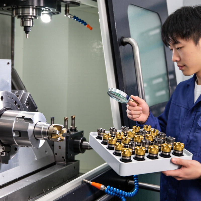
Do not trust a catalog alone. Run a controlled test with one tool diameter and stable workholding. Record cutting speed, feed rate, depth of cut, and coolant use. I once blamed the coating for poor tool life, but excessive feed caused the real damage. That mistake changed my inspection routine. Examine the edge under magnification after each trial. If chips become blue, edges crumble, or the surface turns rough, reduce heat or change the tool system. A reliable choice is built from measured results, not assumptions.

Select Tool Geometry for Accuracy, Speed, and Chip Control

10 Tips for Choosing CNC Cutting Tools

Select tool geometry according to accuracy, speed, and chip control. Start with the workpiece material, because aluminum, steel, and hardened alloys need different cutting edges. Choose a positive rake for lower cutting forces and cleaner finishes. Use a stronger, smaller rake when interrupted cuts create impact. Match the relief angle to the material and machine rigidity. Too little relief causes rubbing, while excessive relief weakens the edge. I have seen a sharp tool fail quickly when the setup allowed vibration.

Check the helix angle before chasing higher feed rates. A higher helix can evacuate chips smoothly from softer materials. A lower helix may improve edge strength in tougher alloys. Select flute count carefully. Fewer flutes create more chip space, but more flutes can increase productivity on rigid machines.

Choose a nose radius that supports the required finish without adding deflection. A large radius is not always better. It may leave chatter marks on a flexible setup.

Inspect the chipbreaker geometry for the actual cutting range. A design made for heavy cuts may perform poorly during light finishing. Keep tool runout low, since uneven loading damages accuracy and chip formation. Confirm the edge preparation, especially for abrasive materials.

Test one variable at a time when results are unclear. That discipline prevents expensive guesses. Geometry charts offer useful guidance, yet shop conditions remain decisive.

Temperature, coolant delivery, clamping, and machine wear can change the result. Recheck the tool after a failed cut, rather than blaming feed speed immediately.

Choose the Correct Tool Size, Flute Design, and Edge Type

10 Tips for Choosing CNC Cutting Tools

Tip: Match the tool size to the machine, material, and cutting depth. A large cutter removes material quickly, but it needs strong spindle power and workholding. A small cutter reaches narrow corners and leaves finer details. However, it deflects more easily. I usually check the tool’s diameter against the pocket width before setting feed rates. My first choice is not always correct, especially when the material varies across one sheet.

Tip: Select flute design according to chip removal and heat control. Two-flute tools often provide more space for chips in softer materials. Three or four flutes can improve finish quality when the machine remains rigid. Too many flutes may trap chips during aggressive cutting. Watch the sound and inspect the chips. Powder-like chips can indicate excessive heat or an unsuitable feed rate.

Tip: Choose the edge type for the cut, not merely the material. Upcut edges clear chips effectively, while downcut edges can leave a cleaner top surface. Compression edges help reduce surface tearing in laminated boards. For abrasive materials, a stronger edge may last longer, but it can require slower cutting parameters. There is no universal setting. Test a small section, measure the result, and adjust one variable at a time.

Set Cutting Parameters and Check Tool Performance

Set Cutting Parameters and Check Tool Performance

Choosing a CNC cutting tool means matching speed, feed, depth, and material. Start with the tool maker’s recommended cutting range, then adjust it for machine rigidity, workholding, coolant, and tool overhang. Cutting speed controls heat, while feed per tooth controls chip thickness. A useful first check is the chip itself. Powdery chips suggest rubbing; long, glowing chips suggest excessive heat.

Record spindle load, vibration, sound, burr formation, and surface finish during the first few passes. McKinsey Global Institute reports that predictive maintenance can reduce machine downtime by 30–50%. Even a simple spreadsheet can support this approach. Log tool number, material, cutting parameters, cycle time, and measured wear. Small records often reveal large problems.

ISO 8688 provides standardized methods for evaluating milling tool life. A practical shop threshold is about 0.3 mm flank wear, but it is not universal. I once increased feed because the surface looked acceptable, then discovered edge chipping under magnification. That was a costly reminder. Check the cutting edge, not only the finished part. Reduce speed when heat staining appears, and reduce feed when chatter or edge damage develops. Do not change several parameters together. Otherwise, the result becomes difficult to interpret. Candor matters here: recommended values are starting points, not guarantees.

Powder Coat Booths

For those larger-sized parts, or smaller quantity runs, we have 2 independent powder coat booths and ovens. The quality, durability and affordability of today’s powder coating finishes make this the process of choice for world-class companies.

Powder coating advantages over other forms of coating are many. Materials used in the Powder coating process can be metals and non-metals that come in a multitude of thicknesses, textures, colors, etc. Another of Powder coating’s biggest advantages over conventional coatings is its ability to create finishes in many different textures. Powder Coating Booths allow us the ability to apply these advantages to large products.

Wet Paint Line

Tri-State Fabricators runs a full-service conveyor line for painting. Wet painting can provide protection or decoration to many different part styles. From start to finish, every project is easier to undergo random and point-based inspection by our skilled painting team.

Advantages to our Wet Paint Line are these lines start with product prep and ends with a thorough inspection of a high quality finished product. Our ability to complete large and small projects with a superior finish and doing so in a timely and economical fashion. This passes along the savings in production to our customers. When powder coating ins not an option, our Wet Paint Line gets the job done right the first time.

Wet Paint Booths

When the parts get big and heavy we roll-out our custom paint racks and oversize booth. By utilizing our partnerships with all the major paint brands, we can match virtually any color with wet paint.

The advantages of having access to a Wet Paint Booth are many. Large projects of many different shapes can be loaded into the booth. The Wet Paint Booth offers an environment that is much more controlled than a typical parts painting operation.

Not only are they used because of their controlled environment, but they’re are also advantageous when it comes to applying paint to parts that are needed in industries that require specialty coatings such as medical, aerospace, etc.

Military CARC

Our military forces have some very high standards when it comes to the finish of their vehicles and equipment. From the first pre-treatment step to final coat, it takes a great deal of knowledge and experience to protect the men and women of our armed forces. They deserve only the best, and Tri-State Fabricators provides it.

All of our processes are closely monitored by our staff and management teams. Both of which are highly trained in the processes of metal fabrication and finishing. Tri-State Fabricators’ goal is to always fully satisfy each and every customer, including the military. We will always put a 110% into what we do.

Glass-Bead Blasting

Abrasive media blasting is an excellent way to remove old paint, rust, and increase the paint/powder adhesion. Glass beads produce a much smoother and brighter finish than angular abrasives; leaving the part clean yet without any dimensional change. Chemically inert and environmentally friendly, we can recycle our beads approximately 30 times; making them a more preferred method of metal cleaning or surface finishing.

Advantages to Glass Bead Blasting are many. Glass bead blast media is used when a project is needing rough surfaces need to become smooth for applications of coatings such as paint. It is typically used to clean paint and rust from a product surface without deforming the surface it is being used on. Overall, compared to many other blasting media, Glass Bead Blasting is a very economical choice and those savings are always passed on to our customers.

Part Washing

Tri-State Fabricators utilize a zinc phosphate wash to clean and etch the material to ensure the best paint adhesion possible. The unique design of our 3-stage wash system does the work like a 5-stage. From Cleaning and rinsing to conversion coating and post-treatment, Our Part Washing process is a complete service and works throughout the fabrication service and the finishing service.

Along with the previously mentioned benefits, Curing is a vital chemical reaction that leaves the product finish hard and relatively safe from mild abrasion and aggressive corrosion. This process can be done in more than one way; ambient air-dry or in curing ovens at temps that exceed 240°.

Burn-Off Oven

From fixing paint mistakes (someone else’s of course) to simply cleaning our paint line hooks, our burn-off oven is put to good use. After a quick burn-off, a little clean up, and a fresh coat of paint, your parts will look better than new.

Why does our Burn-Off Oven work so well? Because super heating the air around parts turns the materials into ashes. From paint and powder coatings to rubber and machining oils, high temps do the job without degrading the integrity of the part.

Masking

Masking is a vital part of producing high quality products. We have die-cut masking patterns to protect machined surfaces as well as a wide range of plugs and caps to protect threaded holes and bolts. We provide permanent and temporary masking.

Masking allows the selected sections of a product to be protected from a fabrication or finishing service. This can be with both chemicals when etching and tapes, paints when only finishing just a section of the product. Masking is great in aiding the customization process of a project.

Screen Printing

Screen printing is a photographic process that transfers artwork onto a porous nylon screen which allows colored ink to flow through the screen and be deposited on an aluminum or plastic component. We can generally have just about any design created onto a screen for your parts.

Some of the advantages of Screen Printing are, brand recognition for your business displaying on your products, assembly instructions, product warnings/hazards, etc. Tri-State Fabricators produces Screen Printing of the highest quality so you know it’s durable.

Metal Finishing

Metal Finishing is the art of treating the exterior portion of product, often metal but can also be made of other materials, so that the surface is clean and free of any debris. Then the process of applying coats or either paint of powder coat takes place. This coating process improves the quality of the product in both appearance and resistance to wear and corrosion.

Tri-State Fabricators, Inc., understands that a project typically isn’t complete until a high-quality finish has been added to your product. This is why our painting and powder coating teams continuously inspect the products throughout the Metal Finishing process.