

Choosing the right Sbma Connector in 2026 takes more than comparing prices or connector dimensions. A small mismatch can affect signal performance, installation time, and long-term reliability. Start with the equipment it must connect to, then verify the mating interface against the manufacturer’s drawings. Names can be confusing. Do not rely on a product title alone.
Frequency range and impedance deserve careful attention, especially in compact RF assemblies. Check the datasheet for supported operating conditions, insertion loss, and return loss where those values matter to your design. Then consider the real installation: available clearance, cable type, expected mating cycles, and exposure to vibration, moisture, or temperature changes. A connector that fits on a bench may be awkward inside a crowded enclosure. Details matter.
This guide explains how to compare those requirements and assess build quality without treating marketing claims as test results. Look for traceable specifications, clear dimensional drawings, and consistent quality documentation. When possible, confirm critical measurements with a qualified supplier or test setup before committing to a large order. I would not choose from a headline specification alone; it can omit the limitation that matters most. No single option suits every application. The best choice balances verified electrical performance, mechanical fit, durability, and cost for the intended system.
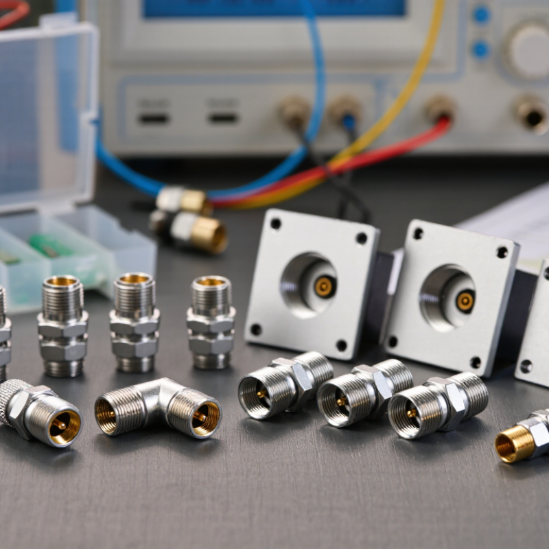
An SBMA connector is a 50 Ω radio-frequency interface designed for blind mating. Two assemblies connect as they slide into position, often inside a chassis. The contact faces may not be visible during installation. No cable wrenching. The 50 Ω value describes the intended impedance; it does not guarantee that the complete signal path will perform well.
Choosing one means checking more than the mating interface. Confirm the operating frequency, allowable insertion loss, return loss, and power needs for your system. Then check the mechanical details: mounting depth, alignment range, and how much movement the connector can tolerate. A small offset between modules can affect contact and RF performance. Measure the actual stack-up, not just the drawing.
Look closely at how the connector will be installed and serviced. Repeated mating, vibration, and dust near the interface can change performance over time. Ask for test data across the frequency range you plan to use, and verify it in a representative assembly. A datasheet alone may leave gaps. I would also inspect a sample after several mating cycles; it is an easy step to overlook when schedules get tight.

For an SBMA assembly, treat 18–22 GHz as a comparison range, not a guaranteed operating window. IEC 61169-33 describes BMA-series RF coaxial connectors, while actual limits depend on the connector design and test conditions. Check the specified frequency range, impedance, and mating configuration before comparing parts. Small differences matter. At 22 GHz, a short adapter, cable bend, or imperfect mate can affect measured return loss.
Ask for insertion-loss and VSWR data across the full band, not a single value at the upper limit. A plot is more useful than a headline rating. IEC 61169-33 provides a standards reference; NIST Technical Note 1297 explains how measurement uncertainty should be evaluated and reported. Request the test fixture details, calibration method, and sample count, too. One sample can look unusually good. In practice, allow margin below the rated ceiling when the link must perform reliably, and verify the assembled path under its real mounting conditions. I would not assume every “22 GHz” label means equal performance.
An SBMA connector can look solid and still weaken a high-frequency signal. Check its voltage standing wave ratio (VSWR) and insertion loss across the full operating band, not just at one convenient test frequency. A single reading can hide a mismatch near the band edge. That matters.
Use a calibrated vector network analyzer and suitable test cables. Measure at the lowest and highest intended frequencies, with several points between them. Record the setup, including cable length and adapter use, so another test can reproduce it. VSWR indicates how much energy reflects back toward the source; lower values generally mean a better impedance match. Insertion loss shows how much signal is lost through the connection. Compare both results with the connector’s specification and your system’s loss budget.
Keep the mating surfaces clean. Seat the connector fully, and use the specified torque if the design calls for it. Then repeat the measurement after reconnecting it. Small setup errors can skew results. It is easy to blame the connector when a worn test cable or loose adapter is responsible. A slightly uneven trace deserves a second look, not an excuse. If results change between repeated connections, investigate the interface and test setup before choosing a part.
Mechanical fit involves more than matching connector names. Check the interface drawing for body dimensions, mounting cutout, mating depth, and alignment tolerances. Nominal dimensions alone may hide a problem. A small offset can put uneven pressure on contacts or prevent full seating. Small gaps matter.
Confirm allowable axial and angular misalignment, especially when connectors meet inside a chassis. Account for tolerance stack-up across panels, brackets, and cable assemblies. A quick bench fit can still mislead; it may not reproduce panel flex or cable pull. Test a representative assembly, and inspect whether both mating faces sit evenly.
Review how the connector engages. Follow its specified mating method and seating limits; do not force it. Do not force it. For threaded interfaces, use the stated torque; for other mechanisms, verify the required travel and locking action. Then compare cycle-life data, noting the test conditions and what counts as failure. A cycle rating is not a guarantee under every installation. After repeated mating, check for looseness, visible wear, rising contact resistance, or degraded RF performance. Record results at intervals. If the supplier’s cycle-life conditions differ from your use case, request clarification before selecting the part.
When selecting an SBMA connector, verify the mating interface against the applicable MIL-STD-348 revision—not just the product name. MIL-STD-348B documents interface dimensions for many RF connector series, but an “SBMA” label alone does not prove dimensional interchangeability. Compare the drawing’s mating-plane position, center-contact geometry, outer-conductor dimensions, and coupling method with the connector specification. Small mismatches can cause poor contact or damage. It happens.
Check the actual parts, too. Measure critical features with suitable inspection tools, and confirm tolerances in the manufacturer’s technical drawing. Then verify system impedance, frequency range, and blind-mate alignment requirements separately; dimensional fit does not guarantee electrical performance. A connector may seat smoothly yet still show unstable readings after repeated mating. MIL-STD-348 provides the interface reference, not a substitute for application-level testing. Record the drawing revision and measurement results, especially when suppliers use different terminology. Real assemblies can be less tidy than drawings suggest, so allow time for a fit check before committing to production.
| Compatibility Check | Dimension or Data to Verify | Reference / Acceptance Basis | Why It Matters |
|---|---|---|---|
| Connector interface identification | Confirm that both mating parts are the same SBMA interface variant and mating style. | Use the connector drawing and the applicable MIL-STD-348 interface drawing; verify the standard edition and figure cited by the supplier. | A similar connector name does not guarantee that the mating geometry is compatible. |
| Outer-conductor interface | Compare the mating-face diameter, mating profile, and axial reference dimensions. | Measure or inspect against the applicable interface drawing. Use its stated units, tolerances, and datums. | Mismatch can prevent full engagement or cause poor electrical contact and mechanical damage. |
| Center contact | Check contact diameter, pin or socket configuration, position, and engagement depth. | Confirm the contact geometry and limits on the applicable MIL-STD-348 interface drawing and component drawing. | Correct center-contact alignment is required for reliable mating and signal continuity. |
| Dielectric and interface plane | Check dielectric location, exposed lengths, and the relative position of the center and outer conductors. | Compare the mating-face cross-section and axial dimensions with the specified interface drawing. | Incorrect dielectric or contact positioning can alter the interface and obstruct proper mating. |
| Blind-mate alignment | Verify the permitted radial and axial misalignment, engagement travel, and any float built into the connector design. | Use the connector manufacturer’s mechanical drawing and system-level alignment requirements; do not assume these values are universal. | Blind-mate performance depends on the complete assembly, not just the connector interface. |
| Mounting and packaging | Check panel cutout, mounting-hole spacing, connector projection, and available mating clearance. | Use the specific component drawing. These package dimensions may be product-specific rather than defined by the mating-interface standard. | A correct RF interface can still fail to fit the panel or assembly. |
| Nominal impedance | SBMA RF connectors are commonly designed for a nominal 50 Ω system; confirm the value for the selected component and equipment. | Check the component datasheet and the system’s RF requirements. | Matching nominal impedance helps maintain compatibility across the RF signal path. |
| Frequency range | Confirm the specified operating frequency range for the exact connector, cable assembly, and mating configuration. | Use published component test data; frequency capability is design-dependent and should not be inferred from the interface name alone. | Frequency limits affect insertion loss, return loss, and overall system performance. |
| Inspection and mating check | Inspect contacts and mating faces for damage, contamination, deformation, or out-of-position features; confirm smooth, complete engagement. | Follow the component instructions and applicable inspection criteria. Do not force parts that do not align. | Physical damage or incomplete engagement can compromise both performance and service life. |
Selection rule: MIL-STD-348 provides interface dimensions for specified connector interfaces; it does not establish one universal dimension set for every product described as SBMA. Verify the exact interface drawing, standard edition, and component drawing before ordering or mating parts.


For those larger-sized parts, or smaller quantity runs, we have 2 independent powder coat booths and ovens. The quality, durability and affordability of today’s powder coating finishes make this the process of choice for world-class companies.
Powder coating advantages over other forms of coating are many. Materials used in the Powder coating process can be metals and non-metals that come in a multitude of thicknesses, textures, colors, etc. Another of Powder coating’s biggest advantages over conventional coatings is its ability to create finishes in many different textures. Powder Coating Booths allow us the ability to apply these advantages to large products.
Tri-State Fabricators runs a full-service conveyor line for painting. Wet painting can provide protection or decoration to many different part styles. From start to finish, every project is easier to undergo random and point-based inspection by our skilled painting team.
Advantages to our Wet Paint Line are these lines start with product prep and ends with a thorough inspection of a high quality finished product. Our ability to complete large and small projects with a superior finish and doing so in a timely and economical fashion. This passes along the savings in production to our customers. When powder coating ins not an option, our Wet Paint Line gets the job done right the first time.
When the parts get big and heavy we roll-out our custom paint racks and oversize booth. By utilizing our partnerships with all the major paint brands, we can match virtually any color with wet paint.
The advantages of having access to a Wet Paint Booth are many. Large projects of many different shapes can be loaded into the booth. The Wet Paint Booth offers an environment that is much more controlled than a typical parts painting operation.
Not only are they used because of their controlled environment, but they’re are also advantageous when it comes to applying paint to parts that are needed in industries that require specialty coatings such as medical, aerospace, etc.
Our military forces have some very high standards when it comes to the finish of their vehicles and equipment. From the first pre-treatment step to final coat, it takes a great deal of knowledge and experience to protect the men and women of our armed forces. They deserve only the best, and Tri-State Fabricators provides it.
All of our processes are closely monitored by our staff and management teams. Both of which are highly trained in the processes of metal fabrication and finishing. Tri-State Fabricators’ goal is to always fully satisfy each and every customer, including the military. We will always put a 110% into what we do.
Abrasive media blasting is an excellent way to remove old paint, rust, and increase the paint/powder adhesion. Glass beads produce a much smoother and brighter finish than angular abrasives; leaving the part clean yet without any dimensional change. Chemically inert and environmentally friendly, we can recycle our beads approximately 30 times; making them a more preferred method of metal cleaning or surface finishing.
Advantages to Glass Bead Blasting are many. Glass bead blast media is used when a project is needing rough surfaces need to become smooth for applications of coatings such as paint. It is typically used to clean paint and rust from a product surface without deforming the surface it is being used on. Overall, compared to many other blasting media, Glass Bead Blasting is a very economical choice and those savings are always passed on to our customers.
Tri-State Fabricators utilize a zinc phosphate wash to clean and etch the material to ensure the best paint adhesion possible. The unique design of our 3-stage wash system does the work like a 5-stage. From Cleaning and rinsing to conversion coating and post-treatment, Our Part Washing process is a complete service and works throughout the fabrication service and the finishing service.
Along with the previously mentioned benefits, Curing is a vital chemical reaction that leaves the product finish hard and relatively safe from mild abrasion and aggressive corrosion. This process can be done in more than one way; ambient air-dry or in curing ovens at temps that exceed 240°.
From fixing paint mistakes (someone else’s of course) to simply cleaning our paint line hooks, our burn-off oven is put to good use. After a quick burn-off, a little clean up, and a fresh coat of paint, your parts will look better than new.
Why does our Burn-Off Oven work so well? Because super heating the air around parts turns the materials into ashes. From paint and powder coatings to rubber and machining oils, high temps do the job without degrading the integrity of the part.
Masking is a vital part of producing high quality products. We have die-cut masking patterns to protect machined surfaces as well as a wide range of plugs and caps to protect threaded holes and bolts. We provide permanent and temporary masking.
Masking allows the selected sections of a product to be protected from a fabrication or finishing service. This can be with both chemicals when etching and tapes, paints when only finishing just a section of the product. Masking is great in aiding the customization process of a project.
Screen printing is a photographic process that transfers artwork onto a porous nylon screen which allows colored ink to flow through the screen and be deposited on an aluminum or plastic component. We can generally have just about any design created onto a screen for your parts.
Some of the advantages of Screen Printing are, brand recognition for your business displaying on your products, assembly instructions, product warnings/hazards, etc. Tri-State Fabricators produces Screen Printing of the highest quality so you know it’s durable.
Metal Finishing is the art of treating the exterior portion of product, often metal but can also be made of other materials, so that the surface is clean and free of any debris. Then the process of applying coats or either paint of powder coat takes place. This coating process improves the quality of the product in both appearance and resistance to wear and corrosion.
Tri-State Fabricators, Inc., understands that a project typically isn’t complete until a high-quality finish has been added to your product. This is why our painting and powder coating teams continuously inspect the products throughout the Metal Finishing process.