

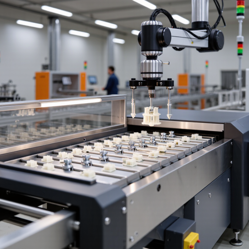
Choosing the right Flexible Feeding System can shape production speed, product quality, and daily operator workload. The best option is not always the fastest or most automated. It must fit the actual parts, process, and factory environment.
Start with the material being handled. Small molded components may feed differently from metal fasteners or delicate assemblies. Note each part’s size, weight, surface, and tendency to tangle. Then consider the required rate, changeover frequency, and space around the machine. A feeder that runs smoothly with one product may struggle when shapes or batch sizes change. That detail is easy to overlook.
A practical evaluation should include more than a brochure specification. Ask suppliers to test representative parts, including awkward or slightly inconsistent samples. Watch how parts orient, recover from jams, and respond to routine adjustments. Check whether operators can clean the system and switch products without lengthy stoppages. Also review controls, guarding, maintenance access, and available technical support. These factors affect reliability over time.
There is no perfect setup. A system optimized for speed may need more careful tuning, while a flexible design may require extra floor space. Be realistic about future product changes, but avoid paying for features the process will not use. Comparing test results, operating needs, and ownership costs gives teams a clearer basis for choosing. The right decision comes from evidence, not assumptions.
How to Choose the Right Flexible Feeding System?
Translate each part into measurable requirements before comparing feeding systems. Record its length, width, and height in millimeters, including the smallest and largest production variants. Measure a sample from the actual process, not just a polished drawing. Small details matter. A 12 mm clip with a narrow hook may behave differently from a simple 12 mm block.
Weigh parts in grams, and note any variation between batches. Mass affects how parts settle and move, but shape, surface finish, and center of gravity matter too. A light, flat plastic part can cling to a bowl or tray; a heavier metal part may collide and change orientation. Test real samples. It sounds obvious, yet this step is easy to skip when schedules are tight.
Set the required feed rate in parts per minute, using the downstream machine’s actual demand and planned operating pauses. If the line needs 40 parts per minute, verify that the feeder can sustain that rate with the chosen part mix, not just during a short demonstration. Include time for orientation and recovery after a misfeed. A rough trial can reveal useful problems, though it should not replace a longer production test. Leave room for uncertainty; calculated rates can look reassuring and still fail on Monday morning.

Choosing a flexible feeding system starts with the real production rate, measured in parts per minute. A stable stream of one small component may suit a centrifugal or vibratory feeder. Delicate parts, however, can scuff or tangle when pushed too aggressively. A step feeder may handle them more gently, though its output can be lower. Check the rate at the point where parts reach the robot or assembly station, not just the feeder’s advertised maximum. A gap in presentation can slow the entire line.
Changeover frequency changes the calculation. If operators switch parts several times per shift, consider how quickly they can replace guides, adjust settings, and load a new vision recipe. A flexible feeder can reduce dedicated tooling, but it still needs sensible setup procedures. The awkward truth: fast changeovers on a demo bench may take longer beside a running line. Time the process with actual parts. Count good, correctly oriented parts for several minutes, then repeat after a changeover. Leave room for variation; parts from different batches may behave differently. A brief trial may not reveal every snag.
Size Vision and Robotics by Pick Rate, Accuracy (mm), and Payload (kg)
Choose a system against real production conditions, not a best-case demonstration. Define pick rate as successful picks per minute over a sustained run, including replenishment and missed picks. The International Federation of Robotics reported 541,302 industrial robot installations worldwide in 2023 in World Robotics 2024. That figure shows automation’s scale, but it does not predict your feeder’s throughput. Part shape, surface finish, and bowl density matter. A clean lab demo can still mislead.
Tips: Test your actual parts. Record good picks per minute, mis-picks, and recovery time.
Specify accuracy in millimeters at the pickup point, not only the robot’s repeatability. ISO 9283 covers industrial robot performance measures, including pose accuracy and repeatability; vision calibration and tool alignment add their own errors. A 1 mm target may be too loose for a small connector, yet excessive for a large molded part. Check the complete tolerance stack. For payload in kilograms, include the gripper, cables, and workpiece, then allow for acceleration and off-center loads. I would leave margin rather than size to the brochure maximum; it costs space, but avoids a fragile setup.
A flexible feeding system may combine a camera, vibrating bowl, conveyor, and robot in one compact cell. That layout can change whenever parts or recipes change. Verify the complete robot cell against the applicable edition of ISO 10218, not just the robot arm’s documentation. The standard addresses industrial robot safety and integration; confirm which edition and adoption apply to your project.
Start with a documented risk assessment. Check reach-through gaps, access doors, interlocks, presence-sensing devices, and stopping distances. A safety scanner may need a larger protective field when the robot carries a long part. Test safeguards at the actual operating speed and with the real tooling installed. Small details matter. An emergency-stop button is not a substitute for guarding or other required protective measures.
Review operating modes too: production, loading, fault recovery, and maintenance can create different risks. Confirm that safety-related control functions are designed, tested, and validated for the assessed hazards. Keep test records, including measured stopping times and any changes to feeder positions or robot programs. Do not assume. A tidy cell can still have a blind spot near a bin or service panel, and that is easy to overlook during commissioning. Have qualified personnel review the final setup before routine use.
Use this checklist when assessing a flexible feeding system that includes a robot, feeder, tooling, sensors, and cell controls. Confirm the applicable edition of ISO 10218 and local regulations for the installation.
| Safety dimension | What to verify | Evidence or acceptance check | Relevant reference |
|---|---|---|---|
| Risk assessment and system boundaries | Assess the complete application—not only the robot—including feeding equipment, end effector, workpieces, conveyors, operator tasks, and foreseeable misuse. | Document hazards, operating modes, people exposed, risk-reduction measures, and residual risks for setup, production, recovery, cleaning, and maintenance. | ISO 10218-2; ISO 12100 |
| Robot and cell integration | Confirm that the robot, feeder, tooling, safety devices, and control system are integrated as a coordinated robot application. | Review integration documentation, safety functions, operating instructions, and validation records for the completed cell. | ISO 10218-1; ISO 10218-2 |
| Access prevention and safeguarding | Identify access points and protect people from hazardous robot motion, pinch points, ejected parts, and moving feeder components. | Check guard construction, openings, access doors, and safety-device coverage against the risk assessment. Verify that reaching around, over, or under safeguards does not create an unprotected route. | ISO 10218-2; ISO 14120; ISO 14119 |
| Safety distances and presence sensing | Where scanners, light curtains, or other presence-sensing devices are used, account for approach direction, stopping time, and the possibility of reaching into the hazard zone. | Record the calculation and verify the installed protective distance using measured stopping performance and the device manufacturer’s instructions. | ISO 13855; ISO 13857 |
| Safety-related control functions | Set the required performance of each safety function from the risk assessment. Consider guard interlocking, protective stops, enabling devices, and safe speed or position functions where applicable. | Document the required and achieved performance level or safety integrity level, architecture, diagnostic measures, and validation results. | ISO 13849-1; IEC 62061 |
| Emergency stop | Provide accessible emergency-stop devices for the application and ensure that activating one initiates the intended stop response. | Test each device, confirm that reset does not restart the cell, and verify that emergency stop is treated as a complementary protective measure—not a substitute for guarding. | ISO 10218-2; ISO 13850 |
| Setup, teaching, and recovery | Review how authorized personnel enter the cell for teaching, fault recovery, jam clearing, and adjustment. Consider reduced-speed operation and enabling controls where required. | Verify mode selection, access control, stop behavior, and restart conditions. Ensure personnel can perform necessary tasks without bypassing safeguards. | ISO 10218-1; ISO 10218-2 |
| Collaborative operation | If people may share space with the robot, define the intended collaborative method and assess the robot, tool, workpiece, and application together. | Validate the selected protective measures and operating conditions. A collaborative-rated robot alone does not make the entire application safe for human contact. | ISO 10218; ISO/TS 15066 |
| Feeder, tooling, and workpiece hazards | Check for sharp or hot parts, stored energy, entanglement, ejected components, and pinch or crush points created by feeders, grippers, and transfer mechanisms. | Confirm that guarding, interlocks, safe loading methods, and instructions cover hazards beyond the robot’s reach and motion envelope. | ISO 10218-2; ISO 12100 |
| Electrical equipment and isolation | Assess electrical hazards and energy sources, including pneumatic or hydraulic energy, during servicing and fault recovery. | Verify electrical protection, isolation points, identification, and documented procedures for preventing unexpected start-up and releasing stored energy. | IEC 60204-1; ISO 14118 |
| Validation and change management | Reassess safety when changing the robot program, feeder layout, tooling, workpiece, speed, or protective-device configuration. | Keep test records for safety functions and stopping performance, plus updated risk assessments, drawings, instructions, and training records. | ISO 10218-2; ISO 12100 |
Selection rule: Choose a flexible feeding system only after the integrated application has been risk-assessed and its safeguards and safety functions have been validated. Applicable standards and legal requirements depend on the country, installation date, and system configuration.
When comparing flexible feeding systems, purchase price tells only a small part of the story. Track overall equipment effectiveness (OEE), mean time between failures (MTBF), and changeover time under real production conditions. A feeder may run smoothly on one part but struggle with another’s shape or surface. Test representative components, including the awkward ones.
OEE shows how much planned production time becomes usable output. Record stops, speed loss, and rejected parts across multiple shifts. MTBF can indicate reliability, but a single average may hide repeated minor faults. Ask operators to log jams, sensor adjustments, and time spent clearing parts. Small interruptions add up. Check maintenance records, too; estimates without consistent records deserve caution.
Changeover time affects both labor and available production hours. Measure the full task, from the last good part of one run to the first accepted part of the next. Include bowl or track cleaning, recipe selection, and validation. Then calculate lifecycle cost using expected run hours, service needs, spare parts, and realistic changeover frequency. These inputs are not perfect. Product mix may change, and trial conditions can flatter performance. Keep the assumptions visible, and compare systems using the same parts and operating schedule.


For those larger-sized parts, or smaller quantity runs, we have 2 independent powder coat booths and ovens. The quality, durability and affordability of today’s powder coating finishes make this the process of choice for world-class companies.
Powder coating advantages over other forms of coating are many. Materials used in the Powder coating process can be metals and non-metals that come in a multitude of thicknesses, textures, colors, etc. Another of Powder coating’s biggest advantages over conventional coatings is its ability to create finishes in many different textures. Powder Coating Booths allow us the ability to apply these advantages to large products.
Tri-State Fabricators runs a full-service conveyor line for painting. Wet painting can provide protection or decoration to many different part styles. From start to finish, every project is easier to undergo random and point-based inspection by our skilled painting team.
Advantages to our Wet Paint Line are these lines start with product prep and ends with a thorough inspection of a high quality finished product. Our ability to complete large and small projects with a superior finish and doing so in a timely and economical fashion. This passes along the savings in production to our customers. When powder coating ins not an option, our Wet Paint Line gets the job done right the first time.
When the parts get big and heavy we roll-out our custom paint racks and oversize booth. By utilizing our partnerships with all the major paint brands, we can match virtually any color with wet paint.
The advantages of having access to a Wet Paint Booth are many. Large projects of many different shapes can be loaded into the booth. The Wet Paint Booth offers an environment that is much more controlled than a typical parts painting operation.
Not only are they used because of their controlled environment, but they’re are also advantageous when it comes to applying paint to parts that are needed in industries that require specialty coatings such as medical, aerospace, etc.
Our military forces have some very high standards when it comes to the finish of their vehicles and equipment. From the first pre-treatment step to final coat, it takes a great deal of knowledge and experience to protect the men and women of our armed forces. They deserve only the best, and Tri-State Fabricators provides it.
All of our processes are closely monitored by our staff and management teams. Both of which are highly trained in the processes of metal fabrication and finishing. Tri-State Fabricators’ goal is to always fully satisfy each and every customer, including the military. We will always put a 110% into what we do.
Abrasive media blasting is an excellent way to remove old paint, rust, and increase the paint/powder adhesion. Glass beads produce a much smoother and brighter finish than angular abrasives; leaving the part clean yet without any dimensional change. Chemically inert and environmentally friendly, we can recycle our beads approximately 30 times; making them a more preferred method of metal cleaning or surface finishing.
Advantages to Glass Bead Blasting are many. Glass bead blast media is used when a project is needing rough surfaces need to become smooth for applications of coatings such as paint. It is typically used to clean paint and rust from a product surface without deforming the surface it is being used on. Overall, compared to many other blasting media, Glass Bead Blasting is a very economical choice and those savings are always passed on to our customers.
Tri-State Fabricators utilize a zinc phosphate wash to clean and etch the material to ensure the best paint adhesion possible. The unique design of our 3-stage wash system does the work like a 5-stage. From Cleaning and rinsing to conversion coating and post-treatment, Our Part Washing process is a complete service and works throughout the fabrication service and the finishing service.
Along with the previously mentioned benefits, Curing is a vital chemical reaction that leaves the product finish hard and relatively safe from mild abrasion and aggressive corrosion. This process can be done in more than one way; ambient air-dry or in curing ovens at temps that exceed 240°.
From fixing paint mistakes (someone else’s of course) to simply cleaning our paint line hooks, our burn-off oven is put to good use. After a quick burn-off, a little clean up, and a fresh coat of paint, your parts will look better than new.
Why does our Burn-Off Oven work so well? Because super heating the air around parts turns the materials into ashes. From paint and powder coatings to rubber and machining oils, high temps do the job without degrading the integrity of the part.
Masking is a vital part of producing high quality products. We have die-cut masking patterns to protect machined surfaces as well as a wide range of plugs and caps to protect threaded holes and bolts. We provide permanent and temporary masking.
Masking allows the selected sections of a product to be protected from a fabrication or finishing service. This can be with both chemicals when etching and tapes, paints when only finishing just a section of the product. Masking is great in aiding the customization process of a project.
Screen printing is a photographic process that transfers artwork onto a porous nylon screen which allows colored ink to flow through the screen and be deposited on an aluminum or plastic component. We can generally have just about any design created onto a screen for your parts.
Some of the advantages of Screen Printing are, brand recognition for your business displaying on your products, assembly instructions, product warnings/hazards, etc. Tri-State Fabricators produces Screen Printing of the highest quality so you know it’s durable.
Metal Finishing is the art of treating the exterior portion of product, often metal but can also be made of other materials, so that the surface is clean and free of any debris. Then the process of applying coats or either paint of powder coat takes place. This coating process improves the quality of the product in both appearance and resistance to wear and corrosion.
Tri-State Fabricators, Inc., understands that a project typically isn’t complete until a high-quality finish has been added to your product. This is why our painting and powder coating teams continuously inspect the products throughout the Metal Finishing process.