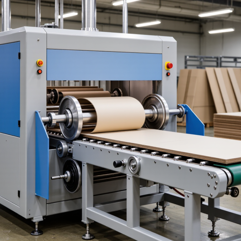
A Chipboard Slotting Machine is a precision system designed to cut slots, notches, and folding lines in chipboard sheets. It prepares flat board for cartons, partitions, displays, and protective packaging. The machine usually combines sheet feeding, alignment, scoring, slotting, and waste removal. Each stage affects the final fold.
Packaging machinery engineer Martin Keller describes the principle clearly: “Accurate slotting begins with stable feeding, because every later cut depends on the first position.” This practical observation explains why operators watch the infeed table closely. A slightly tilted sheet can create uneven slots, cracked edges, or a carton that refuses to close.
During operation, rollers pull the chipboard through the machine. Rotary knives or shaped cutting tools remove narrow sections at programmed positions. Creasing tools may press folding lines without cutting through the material. Sensors check sheet presence and alignment. Some advanced models adjust tool spacing through digital controls, while simpler machines depend more heavily on manual setup.
The result should be clean and repeatable. It should also be checked by hand. Run your finger along the slot edge. Feel for loose fibers. Inspect the first few sheets before increasing speed. Small defects often become larger production losses.
The process sounds straightforward. It is not always forgiving. Board thickness, moisture, knife sharpness, and feeding pressure can change performance. This guide explains what a Chipboard Slotting Machine does, how its working stages connect, and why careful setup matters more than impressive speed. There is room for improvement in every line, especially when real materials behave differently from specifications.
A chipboard slotting machine is a workshop tool for cutting narrow, accurate grooves in chipboard panels. Chipboard is made from compressed wood particles, so clean cutting requires stable support and controlled pressure. The machine usually includes a feed table, cutting blade, guide fence, depth adjustment, and dust collection system. Together, these parts create slots for folding, joining, edging, or inserting connecting components.
During operation, the panel moves across the cutting area while a rotating blade removes a measured strip of material. The operator sets the slot width, depth, position, and feed speed before cutting. A firm guide helps maintain a straight groove. However, results can change when the board contains uneven particles or internal voids. A perfectly clean slot is not always guaranteed. That limitation deserves attention.
Tips: Test the settings on a scrap panel first. Check the blade condition and measure the groove after cutting. Keep the workpiece flat and supported on both sides. Excessive feed speed may cause chipped edges, while too much pressure can shift the panel. Dust removal also matters because accumulated particles can reduce visibility and affect cutting accuracy. A careful operator reviews each batch instead of assuming every panel will behave identically.
A chipboard slotting machine cuts narrow, controlled grooves into board sheets. Its main workload is laminated or uncoated chipboard used for cartons, displays, dividers, and rigid packaging. Chipboard contains compressed wood fibers, paper particles, and binding agents. Its density can change across one sheet. That variation matters.
Depending on the machine design, it may also handle greyboard, coated paperboard, or certain fiberboard grades. Operators must check thickness, surface finish, moisture, and sheet stiffness before production. Thin board can buckle under pressure. Very dense board can wear the cutting tool faster. A practical setup usually includes a feeding table, guide rails, rollers, and a powered cutting head. Some models use vacuum assistance to control dust and keep the sheet stable.
The machine’s cutting head may contain circular blades, scoring knives, or adjustable slotting tools. These components create grooves at selected widths and depths. Sensors can monitor sheet position, while clamps reduce movement during cutting. A control panel adjusts feed speed, spacing, and tool height. Small changes affect folding accuracy. In practice, the first test sheet is rarely perfect. Operators often find that a guide rail needs a slight correction, especially with warped chipboard. Dull blades can leave torn edges, compressed fibers, or uneven slot bottoms. Regular cleaning and careful tool inspection improve reliability, but they do not replace a real test cut.
A chipboard slotting machine uses a rotating cutter or spindle to produce precise grooves, channels, and slots in sheet materials. Common materials include chipboard, MDF, plywood, and melamine-faced panels. The chart shows representative nominal panel thicknesses frequently used in furniture and cabinet manufacturing; actual machine capacity depends on the cutter, feed system, and machine configuration.
Typical machine components include a worktable, clamping or guiding system, cutting spindle, slotting tool, dust-extraction connection, and numerical or manual control system.
A chipboard slotting machine cuts narrow grooves or openings in rigid chipboard sheets. These slots may support folding, fitting, or later assembly. The machine usually combines a feeding table, adjustable guides, a rotating cutting tool, and a dust extraction system. Its accuracy depends on more than cutting speed. Board thickness, moisture, cutter width, and slot depth all affect the result.
The process starts with checking the sheet for warping, damaged edges, and inconsistent thickness. The operator then enters the slot position, length, width, and depth. Guides hold the board square during feeding. A test piece is useful. The first cut is rarely perfect.
The sheet moves toward the cutter at a controlled speed. The rotating tool removes material along the programmed path, while the guide keeps the groove aligned. Excess dust is drawn away from the cutting area. After cutting, the operator checks the slot with a gauge and measures its position from the board edge. A clean slot should have even walls, a stable depth, and minimal chipping.
Small errors can become obvious during assembly. A slot that is slightly too deep may weaken the panel. A shallow slot may prevent proper fitting. For reliable production, operators should recheck measurements after tool changes and monitor cutter wear. This step is often overlooked.
A chipboard slotting machine cuts narrow grooves into chipboard panels for joints, fittings, or assembly guides. The main types are manual, semi-automatic, and computer-controlled models. Manual machines suit small workshops and occasional production. An operator positions the panel, sets the fence, and activates the cutter. They offer direct control, but results depend heavily on steady hands and repeated measurement.
Semi-automatic machines use powered feeding, adjustable stops, and timed cutting cycles. They improve consistency when several panels need identical slots. Computer-controlled machines manage slot position, depth, spacing, and cutting speed through programmed settings. They fit higher-volume work and complicated layouts. However, programming errors can repeat across every panel. That detail is easy to underestimate.
Operating features often include a height-adjustable spindle, replaceable cutting tools, pressure rollers, and a dust extraction port. A clear scale helps operators set the slot accurately. Clamps reduce panel movement during cutting. Good machines also provide guarded cutters, emergency stops, and overload protection. These features support safer, more reliable operation.
Measure twice. Cut once.
Chipboard can chip at the exit point, especially with a dull tool or excessive feed speed. Experienced operators usually test one spare panel before production. The first setting is rarely perfect. Moisture, panel density, and surface coating can alter the result. Regular cleaning matters too, because dust can affect guides, sensors, and moving parts. A practical inspection should check slot depth, edge quality, alignment, and tool wear after each adjustment.
A chipboard slotting machine cuts accurate grooves, slots, and folding lines into rigid paperboard sheets. Rotary knives or shaped blades remove narrow sections without cutting the entire panel. Operators adjust slot width, depth, spacing, and feed speed. These settings control how cleanly a carton folds. In production, dust extraction matters because loose fibers can affect scoring accuracy and machine maintenance.
Chipboard slotting is widely used in folding cartons, protective inserts, retail displays, bookbinding, and lightweight furniture components. Food, beverage, pharmaceutical, and household goods packaging depend on consistent folding geometry. Smithers’ report, The Future of Corrugated Packaging to 2029, forecasts the global corrugated packaging market will exceed 205 billion US dollars by 2029. Although corrugated board differs from chipboard, the figure shows strong demand for efficient paper-based converting. A 2024 folding-carton market analysis also identifies food and beverage packaging as a leading application area. This connection is useful, but not perfect.
Tips: Test every board grade before full production. Moisture changes cutting behavior. Keep blades sharp and inspect grooves under side lighting. Operators sometimes trust machine settings too much. That is a mistake. A short trial sheet can reveal crushed edges, uneven slots, or weak folding points before material waste becomes expensive. For high-volume work, record blade wear, sheet thickness, and rejected pieces. These simple records improve repeatability and support better process decisions.
| Category | Data Dimension | Typical Industrial Information | Function or Application |
|---|---|---|---|
| Machine Definition and Operating Principle | |||
| Machine Type | Primary purpose | Stationary woodworking machine used to cut straight grooves, channels, rebates, or slots in chipboard panels. | Creates joints, panel recesses, cable routes, back-panel channels, and assembly features. |
| Cutting Method | Material removal | A rotating cutter, grooving saw, or router bit removes a controlled strip of material along a programmed or guided path. | Produces a defined slot width, depth, and position without cutting through the entire panel. |
| Workpiece Positioning | Reference system | Panels are normally positioned against a fence, clamping system, template, or CNC-controlled coordinate system. | Maintains repeatable slot location across batches of furniture or cabinet components. |
| Feed Configuration | Material movement | Manual, semi-automatic, or automatic feed systems may be used depending on production volume and machine design. | Supports prototype work, small-batch production, or continuous industrial manufacturing. |
| Dust Management | Extraction requirement | Local dust extraction is normally connected near the cutting zone to remove wood particles and improve visibility. | Reduces airborne dust, limits contamination, and helps maintain cutting accuracy. |
| Typical Technical Data | |||
| Compatible Materials | Panel types | Uncoated particleboard, melamine-faced chipboard, laminated particleboard, and some veneered board products. | Used for furniture parts, shelving, cabinet sides, partitions, and interior fittings. |
| Common Slot Width | Cutting width | Approximately 3–20 mm for common panel-grooving operations; the actual range depends on the tool and application. | Accommodates back panels, joining splines, dividers, hardware plates, and service channels. |
| Common Slot Depth | Cutting depth | Approximately 2–12 mm for many furniture and cabinet applications, with depth limited by panel thickness and joint design. | Allows recessed features while preserving the structural body of the panel. |
| Typical Panel Thickness | Workpiece thickness | Approximately 8–40 mm for common chipboard components; heavier industrial equipment may handle thicker panels. | Covers thin drawer components, standard cabinet boards, shelving, and structural furniture panels. |
| Cutting Accuracy | Position and dimension control | Well-maintained CNC or guided equipment can commonly achieve approximately ±0.1–0.3 mm positioning accuracy, depending on setup and material quality. | Supports consistent alignment of dowels, biscuits, connectors, shelves, and cabinet backs. |
| Spindle or Cutter Speed | Rotational speed | Woodworking routing systems commonly operate in the range of approximately 12,000–24,000 revolutions per minute. | Provides the cutting speed required for carbide tools used on engineered wood panels. |
| Production Capacity | Operating mode | Manual machines are suitable for low-volume work, while CNC and automatic systems are designed for repeatable batch or production-line operations. | Improves throughput by reducing repeated measuring, marking, and manual routing. |
| Slotting Workflow | |||
| 1. Design Input | Drawing or CNC program | Slot length, width, depth, position, feed direction, and tool diameter are defined before machining. | Provides the dimensional reference for repeatable production. |
| 2. Panel Preparation | Inspection and placement | The panel is checked for correct dimensions, surface condition, edge damage, and orientation before being placed on the table. | Prevents incorrect machining and reduces defects caused by damaged or misaligned panels. |
| 3. Clamping | Workholding | Mechanical clamps, vacuum hold-down, or a combination of both secures the chipboard during cutting. | Limits vibration, panel movement, and dimensional variation. |
| 4. Tool Entry | Cut initiation | The cutter enters the panel at the programmed location or follows a mechanical guide and fence. | Establishes the start point and prevents unintended marks on the workpiece. |
| 5. Slot Cutting | Feed and cutting path | The tool travels along a straight or programmed path while removing material to the specified width and depth. | Forms the required groove, channel, or recessed joint feature. |
| 6. Inspection | Quality control | Operators check slot position, width, depth, edge quality, and surface chipping using gauges or measuring tools. | Confirms that the component is ready for assembly or further processing. |
| Industrial Uses | |||
| Furniture Manufacturing | Cabinets, wardrobes, desks, and shelving | Slots are cut for shelves, dividers, back panels, joining components, and concealed fittings. | Improves assembly accuracy and reduces visible fasteners. |
| Kitchen Cabinet Production | Cabinet carcasses and drawer components | Grooves may be used for cabinet backs, drawer bottoms, connector systems, and alignment features. | Supports modular construction and repeatable cabinet assembly. |
| Office and Commercial Interiors | Partitions, workstations, and storage units | Channels can be machined for cable management, partition components, and removable panels. | Helps integrate electrical and data services into furniture systems. |
| Flat-Pack Furniture | Knock-down components | Precise slots are combined with cams, dowels, biscuits, connectors, or other assembly hardware. | Enables compact packaging and fast on-site assembly. |
| Interior Fit-Out | Wall panels, display units, and built-in storage | Grooves and rebates are used to connect panels and accommodate trims or concealed support parts. | Creates clean lines and repeatable installation details. |
| Retail Fixtures | Shelving and display structures | Repeated slots can receive adjustable shelves, dividers, brackets, or display accessories. | Allows flexible product presentation and component replacement. |
| Automotive and Transport Interiors | Non-structural interior panels | Engineered wood panels may be slotted for trim interfaces, lightweight partitions, or interior fixtures where specified by the design. | Supports accurate fitting of interior components; suitability depends on the approved material and design requirements. |
| Quality, Safety, and Selection Factors | |||
| Edge Quality | Chipping control | Sharp carbide tooling, suitable feed speed, correct rotation direction, and proper support help reduce breakout on faced chipboard. | Improves the appearance and fit of visible furniture components. |
| Tool Selection | Cutter material and geometry | Carbide-tipped or solid-carbide tools are commonly selected for abrasive engineered wood panels. | Provides wear resistance and stable cutting performance. |
| Panel Surface | Finish protection | Melamine, laminate, or veneer surfaces require correct tool direction, support, and feed settings to avoid surface damage. | Protects decorative faces and reduces rework. |
| Operator Safety | Required controls | Guarding, emergency stops, dust extraction, hearing protection, eye protection, and safe workholding are essential. | Reduces exposure to rotating tools, flying particles, noise, and combustible wood dust. |
| Machine Selection | Key decision criteria | Consider slot dimensions, panel size, required accuracy, production volume, automation level, extraction capacity, and available floor space. | Ensures that the machine matches both the product design and manufacturing workload. |

| Note: The technical ranges shown are typical industry reference values rather than universal specifications. Actual performance depends on the machine configuration, cutter geometry, chipboard grade, panel thickness, surface finish, feed rate, and maintenance condition. | |||


For those larger-sized parts, or smaller quantity runs, we have 2 independent powder coat booths and ovens. The quality, durability and affordability of today’s powder coating finishes make this the process of choice for world-class companies.
Powder coating advantages over other forms of coating are many. Materials used in the Powder coating process can be metals and non-metals that come in a multitude of thicknesses, textures, colors, etc. Another of Powder coating’s biggest advantages over conventional coatings is its ability to create finishes in many different textures. Powder Coating Booths allow us the ability to apply these advantages to large products.
Tri-State Fabricators runs a full-service conveyor line for painting. Wet painting can provide protection or decoration to many different part styles. From start to finish, every project is easier to undergo random and point-based inspection by our skilled painting team.
Advantages to our Wet Paint Line are these lines start with product prep and ends with a thorough inspection of a high quality finished product. Our ability to complete large and small projects with a superior finish and doing so in a timely and economical fashion. This passes along the savings in production to our customers. When powder coating ins not an option, our Wet Paint Line gets the job done right the first time.
When the parts get big and heavy we roll-out our custom paint racks and oversize booth. By utilizing our partnerships with all the major paint brands, we can match virtually any color with wet paint.
The advantages of having access to a Wet Paint Booth are many. Large projects of many different shapes can be loaded into the booth. The Wet Paint Booth offers an environment that is much more controlled than a typical parts painting operation.
Not only are they used because of their controlled environment, but they’re are also advantageous when it comes to applying paint to parts that are needed in industries that require specialty coatings such as medical, aerospace, etc.
Our military forces have some very high standards when it comes to the finish of their vehicles and equipment. From the first pre-treatment step to final coat, it takes a great deal of knowledge and experience to protect the men and women of our armed forces. They deserve only the best, and Tri-State Fabricators provides it.
All of our processes are closely monitored by our staff and management teams. Both of which are highly trained in the processes of metal fabrication and finishing. Tri-State Fabricators’ goal is to always fully satisfy each and every customer, including the military. We will always put a 110% into what we do.
Abrasive media blasting is an excellent way to remove old paint, rust, and increase the paint/powder adhesion. Glass beads produce a much smoother and brighter finish than angular abrasives; leaving the part clean yet without any dimensional change. Chemically inert and environmentally friendly, we can recycle our beads approximately 30 times; making them a more preferred method of metal cleaning or surface finishing.
Advantages to Glass Bead Blasting are many. Glass bead blast media is used when a project is needing rough surfaces need to become smooth for applications of coatings such as paint. It is typically used to clean paint and rust from a product surface without deforming the surface it is being used on. Overall, compared to many other blasting media, Glass Bead Blasting is a very economical choice and those savings are always passed on to our customers.
Tri-State Fabricators utilize a zinc phosphate wash to clean and etch the material to ensure the best paint adhesion possible. The unique design of our 3-stage wash system does the work like a 5-stage. From Cleaning and rinsing to conversion coating and post-treatment, Our Part Washing process is a complete service and works throughout the fabrication service and the finishing service.
Along with the previously mentioned benefits, Curing is a vital chemical reaction that leaves the product finish hard and relatively safe from mild abrasion and aggressive corrosion. This process can be done in more than one way; ambient air-dry or in curing ovens at temps that exceed 240°.
From fixing paint mistakes (someone else’s of course) to simply cleaning our paint line hooks, our burn-off oven is put to good use. After a quick burn-off, a little clean up, and a fresh coat of paint, your parts will look better than new.
Why does our Burn-Off Oven work so well? Because super heating the air around parts turns the materials into ashes. From paint and powder coatings to rubber and machining oils, high temps do the job without degrading the integrity of the part.
Masking is a vital part of producing high quality products. We have die-cut masking patterns to protect machined surfaces as well as a wide range of plugs and caps to protect threaded holes and bolts. We provide permanent and temporary masking.
Masking allows the selected sections of a product to be protected from a fabrication or finishing service. This can be with both chemicals when etching and tapes, paints when only finishing just a section of the product. Masking is great in aiding the customization process of a project.
Screen printing is a photographic process that transfers artwork onto a porous nylon screen which allows colored ink to flow through the screen and be deposited on an aluminum or plastic component. We can generally have just about any design created onto a screen for your parts.
Some of the advantages of Screen Printing are, brand recognition for your business displaying on your products, assembly instructions, product warnings/hazards, etc. Tri-State Fabricators produces Screen Printing of the highest quality so you know it’s durable.
Metal Finishing is the art of treating the exterior portion of product, often metal but can also be made of other materials, so that the surface is clean and free of any debris. Then the process of applying coats or either paint of powder coat takes place. This coating process improves the quality of the product in both appearance and resistance to wear and corrosion.
Tri-State Fabricators, Inc., understands that a project typically isn’t complete until a high-quality finish has been added to your product. This is why our painting and powder coating teams continuously inspect the products throughout the Metal Finishing process.