


Choosing the right Cross Slide Table can greatly improve milling accuracy, control, and repeatability. A poor choice may introduce flex, backlash, or frustrating adjustments. This guide reviews ten strong options for hobby workshops, repair benches, and small production environments. Practical fit matters here.
We examine table size, travel range, load capacity, mounting patterns, and adjustment quality. We also consider materials, surface finish, lead screw design, and gib control. These features affect how smoothly a cutter moves across a workpiece. A rigid cast-iron body can resist vibration, while poorly fitted components may create uneven movement. Even a compact table should feel stable under moderate cutting pressure.
The selections reflect manufacturer specifications, common machining requirements, and realistic workshop concerns. However, published measurements do not tell the entire story. Some tables look impressive on paper but need careful setup before delivering reliable results. That is worth remembering. We highlight strengths, limitations, suitable machine sizes, and potential compromises for each model. Readers should verify mounting dimensions, spindle clearance, and intended load before purchasing. No single table suits every milling machine, material, or budget. A thoughtful comparison can prevent expensive mismatches and reduce setup frustration. Expect useful guidance, not absolute promises.
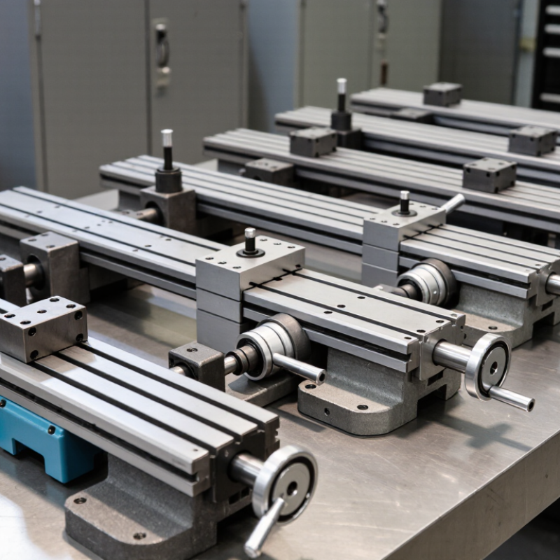
A cross slide table is a compact positioning platform fitted to a milling machine. It moves a workpiece sideways across the cutter, usually through a handwheel and lead screw. Many models also provide forward-and-back movement, creating controlled two-axis adjustment. The table commonly includes T-slots for clamping a vise, fixture, or irregular workpiece.
Its value is practical rather than mysterious. An operator can raise the cutter, secure a steel block, and shift the table in measured increments. Dovetail ways guide the movement and help resist cutting forces. A graduated dial shows travel, but the markings are not always perfectly reliable. Backlash can make the first part of a handwheel turn feel useless. That matters.
When comparing the 10 best cross slide tables for milling machines, check travel, table size, load capacity, screw quality, and locking arrangements. A heavy table may feel stable, yet it can reduce available machine clearance. A small table may fit neatly but flex under aggressive cuts. Measure twice. Check the mounting pattern before ordering, because matching T-slots do not guarantee matching bolt holes. Keep the ways clean and lightly lubricated, then lock unused axes before cutting. Even a well-built table needs adjustment over time. Small errors grow.
For a milling machine, compatibility starts with geometry, not advertising. Measure the table’s mounting slots, bolt spacing, working height, and travel. Then compare those figures with the machine’s throat depth and spindle clearance. A few millimeters can decide whether a vise opens fully. Fit matters.
A practical cross slide table should match the machine’s load capacity and expected cutting forces. Look for rigid cast construction, low-backlash lead screws, lockable axes, and clearly graduated dials. T-slots must accept your existing clamps without improvised washers or drilling. ISO 230-2 provides a useful reference for positioning accuracy and repeatability testing, although many small tables publish limited test data. That gap deserves caution.
The 2024 World Robotics report from the International Federation of Robotics recorded 541,302 industrial robot installations worldwide in 2023. This figure does not measure milling tables, but it reflects a wider demand for repeatable machine movement. A suitable table should therefore return to position consistently after each adjustment. Check stated accuracy under load, not only unloaded movement. Also inspect lubrication points and screw protection, especially in dusty workshops. My own selection mistake would be trusting smooth handwheel movement alone. It can hide flex, backlash, or weak bearings. A dial indicator, a straightedge, and a simple load test reveal more than polished specifications.
Comparison of common cross-slide table configurations using practical machine-tool dimensions. Travel is shown in millimetres, while load capacity is shown in kilograms. Larger travel does not always mean better compatibility; mounting-slot layout, table size, and machine capacity must also be checked.
Selection guideline: match the table’s mounting footprint and slot spacing to the milling machine, then confirm X/Y travel, vertical clearance, and rated load before installation. The values represent standard metric configurations commonly used for manual milling and drilling setups.
Choosing among the 10 best cross slide tables starts with understanding table types, not appearance. A dovetail table offers strong rigidity and resists side movement during heavy milling. It needs careful adjustment, though. If the gib is too tight, movement feels rough. If it is too loose, cutting accuracy suffers.
Ball-bearing tables move smoothly and require less adjustment. They suit light milling, drilling, and repeated positioning. However, their rolling elements may tolerate less shock than a well-adjusted dovetail design. Compound tables add two-axis control, while swivel models help create angled cuts. Compare travel distance, load capacity, mounting-hole patterns, and adjustment access. A long table is not automatically better if it flexes under the workpiece.
Tips: Place a dial indicator on the cutter side and check movement across the full travel. Measure backlash at several positions, not only near the center. Locking screws should hold the table without distorting its alignment. Keep the surface clean; one metal chip can change the reading. In my workshop experience, smooth handwheels can hide unwanted play. I once favored easy movement and overlooked rigidity. That choice produced visible chatter on a small steel bracket. A reliable comparison should include actual test cuts, not specifications alone. Also inspect the lead screw, scale clarity, and replacement parts availability before purchase.
10 Best Cross Slide Tables for Milling Machines?
A cross slide table adds controlled movement along two axes. It helps position a workpiece beneath a milling cutter with greater consistency. The standard manual table suits drilling, slotting, light facing, and small repair work. Its handwheels provide direct feedback, although backlash can affect final dimensions. I always check movement in both directions before cutting. Small errors become obvious on thin parts.
A compound cross slide table is useful for angled drilling and stepped machining. Its upper slide can rotate, while the lower slide supports lateral adjustment. A precision table works better for repeated jobs, jig preparation, and close-fitting components. Look for hardened ways, readable graduations, firm clamps, and smooth lead screws. These details matter more than appearance. A narrow table may improve access, but it limits workpiece size.
Tilting tables support angled milling when the cutter or workpiece needs a controlled incline. Rotary cross slide combinations help create arcs, bolt patterns, and curved slots. They can save setup time, but their scales require careful zeroing. I have seen operators trust the markings too quickly. That is a mistake. Verify the angle with an independent gauge when accuracy matters. Check load capacity, mounting-hole alignment, and available travel before purchase. A stiff table is valuable, yet excessive resistance may indicate poor adjustment rather than quality. The best choice depends on machine rigidity, material, and the precision your work genuinely requires.
A cross slide table only performs as well as its mounting surface. Installation should begin with a clean, rigid machine bed. Remove burrs, oil, and trapped chips. Use a dial indicator to check table alignment before tightening bolts. Tighten gradually, in a cross pattern. The U.S. Department of Energy’s Operations and Maintenance Best Practices Guide reports that preventive maintenance can reduce costs by 12 to 18 percent compared with reactive work. That figure is a useful benchmark. Not a guarantee.
During adjustment, lock one axis and test the other through its full travel. Record backlash at several positions, not only near the center. ISO 230-2:2014 provides methods for evaluating positioning accuracy and repeatability on machine tools. For compact milling setups, even a 0.02 mm change can affect slot width or cutter engagement. Check twice. Do not trust the first reading. Temperature also matters, because a cold table may tighten after several minutes of cutting.
Maintenance is mostly boring, but it protects accuracy. Brush away chips after each session. Wipe the ways clean. Apply the lubricant specified for the mechanism. Inspect the leadscrew, thrust bearings, and gib surfaces for scoring or uneven wear. The DOE guide also identifies lubrication and inspection as core preventive tasks. Actual schedules still depend on load, dust, and operator habits. A monthly interval may suit light use, but heavy cutting demands more frequent checks. More adjustment is not always better. Over-tightening can create drag, heat, and false confidence.
| No. | Cross Slide Table Type | Table Size (L × W) | Longitudinal × Cross Travel | Recommended Load | T-Slot Configuration | Angular Adjustment | Installation Considerations | Adjustment Considerations | Maintenance Requirements | Best Application |
|---|---|---|---|---|---|---|---|---|---|---|
| 1 | Compact Precision Mini Table | 180 × 100 mm | 100 × 60 mm | Up to 25 kg | 2 × 8 mm T-slots | Fixed 90° layout | Mount on a rigid, flat machine surface. Use all available mounting holes and verify that the handwheels clear the machine base. | Remove backlash by lightly tightening the gib screws. Check that the slide moves smoothly across the full travel without binding. | Clean chips after every use. Apply a light way oil before operation and protect the lead screw from abrasive dust. | Small drilling, engraving, model-making, and light aluminum milling. |
| 2 | General Purpose Manual Cross Table | 250 × 145 mm | 150 × 90 mm | Up to 45 kg | 3 × 10 mm T-slots | Fixed 90° layout | Align the table with the machine spindle using an edge finder or dial indicator. Use a solid backing plate when the machine base is thin. | Adjust the gib gradually from both ends. Confirm that the lead screw has consistent resistance and that the table does not rock under hand pressure. | Wipe the ways clean, lubricate the sliding surfaces regularly, and inspect the lead-screw nut for wear or looseness. | Routine workshop milling of aluminum, brass, plastics, and small steel components. |
| 3 | Heavy-Duty Steel-Bodied Cross Table | 300 × 175 mm | 200 × 100 mm | Up to 80 kg | 3 × 12 mm T-slots | Fixed 90° layout | Use a level, rigid mounting surface and high-strength fasteners. Support the table evenly to prevent distortion during tightening. | Set the gib with the table near the center of travel, then verify smooth motion at both travel limits. Recheck alignment after final bolt tightening. | Remove coolant residue and chips immediately. Oil the ways and lead screw, and inspect the mounting bolts for vibration-induced loosening. | Small steel parts, fixtures, repair work, and heavier bench-mill operations. |
| 4 | Extended Travel Long-Range Slide Table | 350 × 180 mm | 250 × 120 mm | Up to 90 kg | 3 × 12 mm T-slots | Fixed 90° layout | Check that the machine column and base can support the extended overhang. Measure parallelism along the entire table length during installation. | Adjust the gib in small increments and test the table at the fully extended positions. Keep the lead screw properly supported to avoid end play. | Lubricate the full length of the ways, not only the center area. Inspect exposed lead-screw threads frequently for chips and dried lubricant. | Long workpieces, drilling patterns, slotting, and multi-position machining. |
| 5 | Rotary Base Swivel Cross Table | 300 × 180 mm | 180 × 100 mm | Up to 65 kg | 3 × 10 mm T-slots | ±45° swivel range | Install with the rotary base fully seated and free of chips. Use an indicator to set the table centerline before locking the swivel mechanism. | Set the swivel angle with a protractor or indicator, then tighten the locking bolts evenly. Check for angular movement after applying cutting pressure. | Clean the rotary interface and lightly oil the locking and sliding surfaces. Keep chips away from the circular locating surfaces. | Angled slots, tapered features, valve work, and compound-position milling. |
| 6 | Fine Adjustment Micrometer-Feed Table | 220 × 140 mm | 120 × 80 mm | Up to 35 kg | 2 × 10 mm T-slots | Fixed 90° layout | Mount on a stable surface and avoid unsupported edges. Confirm that the fine-feed mechanisms remain accessible after the workholding fixture is installed. | Use the coarse feed for positioning and the micrometer feed for final movement. Remove backlash without making the adjustment stiff or intermittent. | Use clean, light oil on the fine-feed screw. Keep the scale, graduations, and screw threads free of coolant and abrasive debris. | Precision layout, light finishing cuts, slot positioning, and inspection-related work. |
| 7 | Wide Platform Fixture-Friendly Table | 400 × 200 mm | 220 × 120 mm | Up to 110 kg | 4 × 12 mm T-slots | Fixed 90° layout | Verify that the machine base has sufficient mounting area. Use a parallel support arrangement and torque mounting fasteners in a crisscross sequence. | Check table flatness after mounting. Adjust the gib so the table remains stable under an offset load while retaining smooth handwheel operation. | Clean the broad platform and T-slots after each job. Apply way oil regularly and inspect the lead-screw bearings for axial play. | Large fixtures, multiple workpieces, production-style drilling, and batch milling. |
| 8 | Fine-Pitch Precision Lead-Screw Table | 300 × 160 mm | 160 × 90 mm | Up to 55 kg | 3 × 10 mm T-slots | Fixed 90° layout | Use a dial indicator to align the table to the spindle axis. Ensure the mounting surface is free from burrs, paint buildup, and embedded chips. | Set the gib for uniform resistance over the complete travel. Check lead-screw backlash at the center and both ends before precision work. | Use the lubricant specified for the slide material. Cover the table during storage and avoid excessive grease that can trap abrasive particles. | Fine interpolation, small-hole patterns, instrument parts, and repeatable manual positioning. |
| 9 | Modular Stackable Cross Table | 250 × 150 mm | 150 × 80 mm | Up to 50 kg | 3 × 10 mm T-slots | Dependent on mounting orientation | Confirm that the stacked arrangement does not exceed the machine's height or stiffness limits. Use dowel references or an indicator for repeatable alignment. | Adjust each axis independently, starting with the lower table. Check for cumulative backlash and make sure both axes remain square after tightening. | Lubricate each slide separately and inspect the interface between stacked tables. Keep all locating faces clean to prevent angular error. | Custom machine setups, compact retrofits, and applications requiring flexible axis arrangement. |
| 10 | Corrosion-Resistant Protected Slide Table | 280 × 160 mm | 170 × 90 mm | Up to 60 kg | 3 × 10 mm T-slots | Fixed 90° layout | Use on machines exposed to coolant or humid environments. Seal or shield mounting interfaces where liquid could collect beneath the table. | Set the gibs after the table reaches normal operating temperature. Verify smooth movement after coolant exposure and check that protective covers do not rub. | Flush away coolant residue, dry the ways, and apply a corrosion-inhibiting way oil. Inspect seals, covers, and drain paths at regular intervals. | Coolant-intensive machining, maintenance workshops, and humid production environments. |


For those larger-sized parts, or smaller quantity runs, we have 2 independent powder coat booths and ovens. The quality, durability and affordability of today’s powder coating finishes make this the process of choice for world-class companies.
Powder coating advantages over other forms of coating are many. Materials used in the Powder coating process can be metals and non-metals that come in a multitude of thicknesses, textures, colors, etc. Another of Powder coating’s biggest advantages over conventional coatings is its ability to create finishes in many different textures. Powder Coating Booths allow us the ability to apply these advantages to large products.
Tri-State Fabricators runs a full-service conveyor line for painting. Wet painting can provide protection or decoration to many different part styles. From start to finish, every project is easier to undergo random and point-based inspection by our skilled painting team.
Advantages to our Wet Paint Line are these lines start with product prep and ends with a thorough inspection of a high quality finished product. Our ability to complete large and small projects with a superior finish and doing so in a timely and economical fashion. This passes along the savings in production to our customers. When powder coating ins not an option, our Wet Paint Line gets the job done right the first time.
When the parts get big and heavy we roll-out our custom paint racks and oversize booth. By utilizing our partnerships with all the major paint brands, we can match virtually any color with wet paint.
The advantages of having access to a Wet Paint Booth are many. Large projects of many different shapes can be loaded into the booth. The Wet Paint Booth offers an environment that is much more controlled than a typical parts painting operation.
Not only are they used because of their controlled environment, but they’re are also advantageous when it comes to applying paint to parts that are needed in industries that require specialty coatings such as medical, aerospace, etc.
Our military forces have some very high standards when it comes to the finish of their vehicles and equipment. From the first pre-treatment step to final coat, it takes a great deal of knowledge and experience to protect the men and women of our armed forces. They deserve only the best, and Tri-State Fabricators provides it.
All of our processes are closely monitored by our staff and management teams. Both of which are highly trained in the processes of metal fabrication and finishing. Tri-State Fabricators’ goal is to always fully satisfy each and every customer, including the military. We will always put a 110% into what we do.
Abrasive media blasting is an excellent way to remove old paint, rust, and increase the paint/powder adhesion. Glass beads produce a much smoother and brighter finish than angular abrasives; leaving the part clean yet without any dimensional change. Chemically inert and environmentally friendly, we can recycle our beads approximately 30 times; making them a more preferred method of metal cleaning or surface finishing.
Advantages to Glass Bead Blasting are many. Glass bead blast media is used when a project is needing rough surfaces need to become smooth for applications of coatings such as paint. It is typically used to clean paint and rust from a product surface without deforming the surface it is being used on. Overall, compared to many other blasting media, Glass Bead Blasting is a very economical choice and those savings are always passed on to our customers.
Tri-State Fabricators utilize a zinc phosphate wash to clean and etch the material to ensure the best paint adhesion possible. The unique design of our 3-stage wash system does the work like a 5-stage. From Cleaning and rinsing to conversion coating and post-treatment, Our Part Washing process is a complete service and works throughout the fabrication service and the finishing service.
Along with the previously mentioned benefits, Curing is a vital chemical reaction that leaves the product finish hard and relatively safe from mild abrasion and aggressive corrosion. This process can be done in more than one way; ambient air-dry or in curing ovens at temps that exceed 240°.
From fixing paint mistakes (someone else’s of course) to simply cleaning our paint line hooks, our burn-off oven is put to good use. After a quick burn-off, a little clean up, and a fresh coat of paint, your parts will look better than new.
Why does our Burn-Off Oven work so well? Because super heating the air around parts turns the materials into ashes. From paint and powder coatings to rubber and machining oils, high temps do the job without degrading the integrity of the part.
Masking is a vital part of producing high quality products. We have die-cut masking patterns to protect machined surfaces as well as a wide range of plugs and caps to protect threaded holes and bolts. We provide permanent and temporary masking.
Masking allows the selected sections of a product to be protected from a fabrication or finishing service. This can be with both chemicals when etching and tapes, paints when only finishing just a section of the product. Masking is great in aiding the customization process of a project.
Screen printing is a photographic process that transfers artwork onto a porous nylon screen which allows colored ink to flow through the screen and be deposited on an aluminum or plastic component. We can generally have just about any design created onto a screen for your parts.
Some of the advantages of Screen Printing are, brand recognition for your business displaying on your products, assembly instructions, product warnings/hazards, etc. Tri-State Fabricators produces Screen Printing of the highest quality so you know it’s durable.
Metal Finishing is the art of treating the exterior portion of product, often metal but can also be made of other materials, so that the surface is clean and free of any debris. Then the process of applying coats or either paint of powder coat takes place. This coating process improves the quality of the product in both appearance and resistance to wear and corrosion.
Tri-State Fabricators, Inc., understands that a project typically isn’t complete until a high-quality finish has been added to your product. This is why our painting and powder coating teams continuously inspect the products throughout the Metal Finishing process.